содержание .. 1 2 3 4 5 6 7 8 9 ..
Aprilia scooter (manual) - part 8
-
-
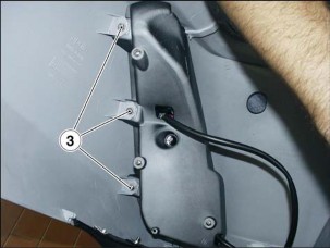
REMOVING THE FRONT DIRECTION INDICATORS
NOTE The procedures described below apply to both direction indicators.

-
Remove both side fairings, 7.1.13.
-
Disconnect the two direction indicator connectors.

-
Release and remove the two screws (1).

-
-
REMOVING THE TAIL LIGHT UNIT

-
Remove the tail, 7.1.5.
RIGHT
-
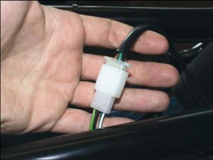
Disconnect the connector (1).
-
Extract the tail light bulb (2).
-
Release and remove the three screws (3).
-
Remove the right light unit.

LEFT
-
Disconnect the connector (1).
-
Release and remove the three screws (4).
-
Remove the left light unit.

-
-
COIL REMOVAL
-
![]()
-
Remove the air dam, 7.1.8.
-
Disconnect the spark plug cap.

-
Disconnect the two coil connectors (1).
-
Release and remove the bolt (2) and collect the nut.

-
CONTROLS
-
THROTTLE CONTROL REMOVAL

-
-
-
Remove the right switch, 7.2.5.
-
Release and remove the two screws (1).
-
Lower the brake master cylinder clamp.

-
Disconnect both throttle cables (2).
-
Remove the brake master cylinder clamp.
-
Remove the brake master cylinder but leave it connected to the brake hose.

-
Release and remove the counterweight retaining screw.
-
Remove the counterweight.

-
Remove the throttle control.

-
REMOVING THE REAR BRAKE MASTER CYLINDER

-
-
Remove the left switch, 7.2.5.
-
Release and remove the two screws (1).
-
Remove the brake master cylinder clamp.
-
Remove the brake master cylinder but leave it connected to the brake hose.
If you have to remove the master cylinder completely:

-
Disconnect the two connectors (2) of the rear brake light.
-
Drain the brake circuit, 2.10.2.
-
Release and remove the screw (3) and collect the sealing washers.
-
Remove the master cylinder.

-
FRAME
-
HANDLEBAR REMOVAL TORQUE WRENCH SETTINGS
Clamp bolt (1) 45 Nm (4.5 kgm)
Safety screw (2) 20 Nm (2.0 kgm)

-
-
-
Remove the handlebar cover, 7.1.17.

-
Remove the throttle control, 7.3.1.
-
Remove the rear brake master cylinder, 7.3.2.
-
Remove the left grip.
-
Release the handlebar from the ties.
-
Slacken the clamp bolt (1).

-
Release and remove the safety screw (2).
-
Remove the handlebar.

-
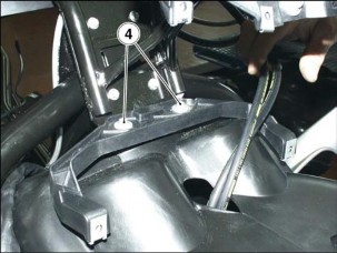
REMOVING THE DASHBOARD/WINDSHIELD MOUNTING BRACKET
TORQUE WRENCH SETTINGS
Screws (2) 12 Nm (1.2 kgm)
Screws (5) 10 Nm (1.0 kgm)

-
-
Remove the headlight, 7.2.7.
-
Remove the dashboard, 7.2.6.
-
Release all ties fitted to the dashboard/windshield mounting bracket.
-
Disconnect the right switch connector.
-
Disconnect the left switch connector.

-
Disconnect the ignition switch connector (1).


-
Take the auxiliary fuse carrier out of its mount.
-
Take the safety relay out of its mount.


-
Release and remove the two retaining screws (2) of the braking system proportioning valve.
-
Release and remove the three retaining screws (3) of the headlight upper mount.
-
Release and remove the two retaining screws (4) of the headlight lower mount.

-
Release and remove the four screws (5) securing the dashboard/windshield mounting bracket to the frame.
-
Remove the dashboard/windshield mounting bracket.
-
SIDE STAND REMOVAL
TORQUE WRENCH SETTINGS
Screws (1) 20 Nm (2.0 kgm)

-
-
Remove the central tunnel, 7.1.7.
-
Disconnect the side stand switch connector.

-
Unhook the two springs from the stand.
-
Release and remove the nut (1).

-
Working from the opposite end, remove in the order: bolt, washer, stand switch and stand.

-
CENTRE STAND REMOVAL
TORQUE WRENCH SETTINGS
Nut (1) 27 Nm (2.7 kgm)
-
-
Place the vehicle on the side stand.
-
Unhook the two springs.

-
Release and remove the nut (1).
-
Withdraw the bolt from the opposite end.
-
Remove the centre stand.
 WARNING
Grease the sliding areas on refitting and avoid
damage to the seals. Tighten the nut and make sure the stand folds up smoothly in the correct position.

-
FRAME REMOVAL
TORQUE WRENCH SETTINGS
Screw (6) 12 Nm (1.2 kgm)
NOTE Certain procedures include cross-references to relevant sections of the manual. Some of the operations described there may not be strictly required for the job at hand. Proceed sensibly to avoid redundant work, that is, always make sure you really need to remove a particular component before proceeding.

-
-
Remove the splashguard, 7.1.18.
-
Remove the headlight, 7.2.7.
-
Disconnect the two horn connectors (1).
-
Release and remove the screw (2).

-
Disconnect the ignition switch connector (3).

-
Release and remove the two screws (4).
-
Remove the fuel tank, 4.1.3.
-
Remove the side stand, 7.4.3.
-
Remove the radiator, 5.3.1.
-
Remove the rear side panels, 7.1.3.
-
Remove the linkages, 7.10.2.
-
Remove the shock absorber, 7.10.1.


-
Disconnect the throttle cable (5) at the carburetor end.
-
Remove the calliper from the rear brake disc, 7.7.5.

-
Release and remove the screw (6).
NOTE Release all cables and hoses from the ties and clips along their full length.

-
Remove the coil, 7.2.10.

-
Disconnect the following connectors:
-
voltage regulator;
-
Engine Control Unit;


-
starter motor connector (7);
-
disconnect the two connectors (8) at the starter relay end.

-
-
Release and remove the two screws (9).
-
Remove the ECU bracket.
-
Lift the frame to remove.
-
FRONT WHEEL
-
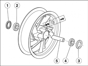
FRONT WHEEL DIAGRAM

Key:
-
Wheel spindle
-
Speedometer drive
-
Right oil seal
-
Right bearing
-
Wheel
-
Inner spacer
-
Left bearing
-
Left oil seal
-
Brake disc
-
Spacer
NOTE Grease the wheel spindle (1).

-
-
FRONT WHEEL REMOVAL
TORQUE WRENCH SETTINGS
Pinch bolt (1) 12 Nm (1.2 kgm)
Wheel spindle 40 Nm (4.0 kgm)
 WARNING
Use great care when removing and refitting the
wheel to avoid damaging the brake hoses, brake discs and brake pads.
-
-
-
Place the vehicle on the centre stand.

-
Place a support underneath the frame.
-
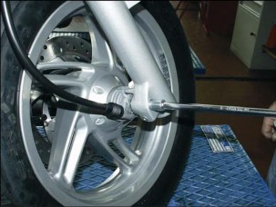
Remove the brake calliper, 7.7.2.
-
Slacken the pinch bolt (1).
-
Release and remove the wheel spindle.
-
Collect the speedometer drive.

-
Remove the wheel.
 WARNING
Do not operate the brake lever with the wheel
removed, or the brake calliper piston might fall out leading to loss of brake fluid.

-
Collect the spacer fitted to the left side of wheel.

-
FRONT WHEEL DISASSEMBLY Read 1.2.1. carefully.

-
-
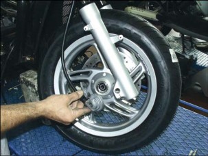
Remove the front wheel, see 7.5.2.
-
Clean both ends of the hub with a cloth.
-
Remove the right oil seal (1).
-
Remove the right bearing (2) using a suitable extractor.
-
Remove the left oil seal (3).
-
Remove the left bearing (4) using a suitable extractor.
 WARNING
Inspect the bearings after each removal, see
7.5.4. and replace as required.
-
Collect the inner spacer (5).
-
Clean the hub bore thoroughly.
-
Wash all components with clean detergent.
 WARNING
Refit the bearings using a drift with the same
diameter as the bearing outer ring. Do not tap the balls or the inner ring.
Make sure to push the following components into firm contact with each other:
-
left bearing (4) with hub;
-
spacer (5) with left bearing (4);
-
right bearing (2) with spacer (5).

-
INSPECTING THE FRONT WHEEL COMPONENTS
 WARNING
Check that all components are in perfect
condition. Pay special attention to the components listed below.
BEARINGS
Rotate the inner ring (1) manually. The ring should turn smoothly, with no hardness or noise.
There should be no end float.
Replace any bearings that do not meet the above requirements.

SEALS
Inspect the seals and replace if damaged or badly worn.
WHEEL SPINDLE
Measure wheel spindle (2) run-out using a dial gauge. Change the spindle (2) if it exceeds the specified limit.
Wheel spindle run-out limit: 0.25 mm.

WHEEL RIM
80 9
70
60
50
1
40 12
30
Use a dial gauge to ensure that wheel rim (3) radial (A) and axial (B) run-out does not exceed the maximum limit allowed.
20
10
0
Exceeding run-out is normally due to worn or damaged bearings.
Replace the bearings first, then re-check run-out. Replace the wheel rim (3) if it still exceeds the maximum limit allowed.
Wheel rim radial and axial run-out limit: 2 mm.
3

TYRE
Check tyre condition, see 2.17.1.

-
содержание .. 1 2 3 4 5 6 7 8 9 ..