Toyota Tundra (2015 year). Manual - part 1594


  Index      Toyota     Toyota Tundra (2015 year) - Service and Repair Manual


Search            copyright infringement  


Content   ..  1592  1593  1594  1595   ..


Toyota Tundra (2015 year). Manual - part 1594


PROCEDURE

1.

READ VALUE USING TECHSTREAM (STARTER SIGNAL)

(a) Connect the Techstream to the DLC3.

(b) Turn the ignition switch to ON and turn the Techstream on.

(c) Enter the following menus: Powertrain / Engine and ECT / Data List / All Data / Starter Signal.

(d) Check the value displayed on the Techstream when the ignition switch is turned to the ON and

START positions.

OK:

IGNITION SWITCH POSITION

STARTER SIGNAL

ON

OFF

START

ON

NG

GO TO STEP 2

OK

CHECK FOR INTERMITTENT PROBLEMS

2.

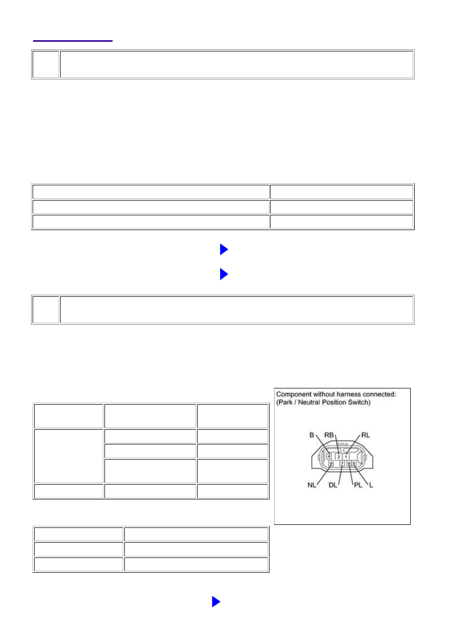
INSPECT PARK/NEUTRAL POSITION SWITCH ASSEMBLY

(a) Disconnect the D35 PNP switch connector.

(b) Measure the resistance according to the value(s) in the

table below.

Standard resistance:

TESTER

CONNECTION

CONDITION

SPECIFIED

CONDITION

4 (B) - 5 (L)

Shift lever position P

Below 1 Ω

Shift lever position N

Below 1 Ω

Shift lever position not

on P or N

10 kΩ or higher

2 (RB) - 5 (L)

All positions

10 kΩ or higher

Result

RESULT

PROCEED TO

NG

A

OK

B

B

GO TO STEP 5

3UR-FBE ENGINE CONTROL SYSTEM: SFI SYSTEM: P0617; Start...

A

NEXT

3.

REPLACE PARK/NEUTRAL POSITION SWITCH ASSEMBLY

(a) Replace the park/neutral position switch 


.

4.

READ VALUE USING TECHSTREAM (STARTER SIGNAL)

(a) Connect the Techstream to the DLC3.

(b) Turn the ignition switch to ON and turn the Techstream on.

(c) Enter the following menus: Powertrain / Engine and ECT / Data List / All Data / Starter Signal.

(d) Check the value displayed on the Techstream when the ignition switch is turned to the ON and

START positions.

OK:

IGNITION SWITCH POSITION

STARTER SIGNAL

ON

OFF

START

ON

NG

GO TO STEP 5

OK

SYSTEM OK

5.

INSPECT IGNITION SWITCH ASSEMBLY

3UR-FBE ENGINE CONTROL SYSTEM: SFI SYSTEM: P0617; Start...

A

NEXT

(a) Disconnect the J9 ignition switch connector.

(b) Measure the resistance according to the value(s) in the

table below.

Standard resistance:

TESTER

CONNECTION

SWITCH CONDITION

SPECIFIED

CONDITION

5 (AM2) - 7 (ST2)

Ignition switch position

LOCK

10 kΩ or higher

Ignition switch position

START

Below 1 Ω

Result

RESULT

PROCEED TO

NG

A

OK

B

B

GO TO STEP 8

6.

REPLACE IGNITION SWITCH ASSEMBLY

(a) Replace the ignition switch 


.

7.

READ VALUE USING TECHSTREAM (STARTER SIGNAL)

(a) Connect the Techstream to the DLC3.

(b) Turn the ignition switch to ON and turn the Techstream on.

(c) Enter the following menus: Powertrain / Engine and ECT / Data List / All Data / Starter Signal.

(d) Check the value displayed on the Techstream when the ignition switch is turned to the ON and

START positions.

OK:

IGNITION SWITCH POSITION

STARTER SIGNAL

3UR-FBE ENGINE CONTROL SYSTEM: SFI SYSTEM: P0617; Start...

NEXT

IGNITION SWITCH POSITION

STARTER SIGNAL

ON

OFF

START

ON

NG

GO TO STEP 8

OK

SYSTEM OK

8.

REPAIR OR REPLACE HARNESS OR CONNECTOR (PNP SWITCH - STA TERMINAL
OF ECM)

9.

CHECK WHETHER DTC OUTPUT RECURS

(a) Connect the Techstream to the DLC3.

(b) Turn the ignition switch to ON.

(c) Turn the Techstream on.

(d) Clear DTCs 


.

(e) Drive the vehicle in accordance with the driving pattern described in the Confirmation Driving

Pattern.

(f) Enter the following menus: Powertrain / Engine and ECT / Trouble Codes.

(g) Read DTCs.

Result

RESULT

PROCEED TO

P0617 is output

A

No DTC is output

B

B

SYSTEM OK

A

REPLACE ECM

3UR-FBE ENGINE CONTROL SYSTEM: SFI SYSTEM: P0617; Start...


Content   ..  1592  1593  1594  1595   ..