Toyota Tundra. Manual - part 400


  Index      Toyota     Toyota Tundra (2007-2010 year) - Service and Repair Manual


Search            copyright infringement  


Content   ..  398  399  400  401   ..


Toyota Tundra. Manual - part 400


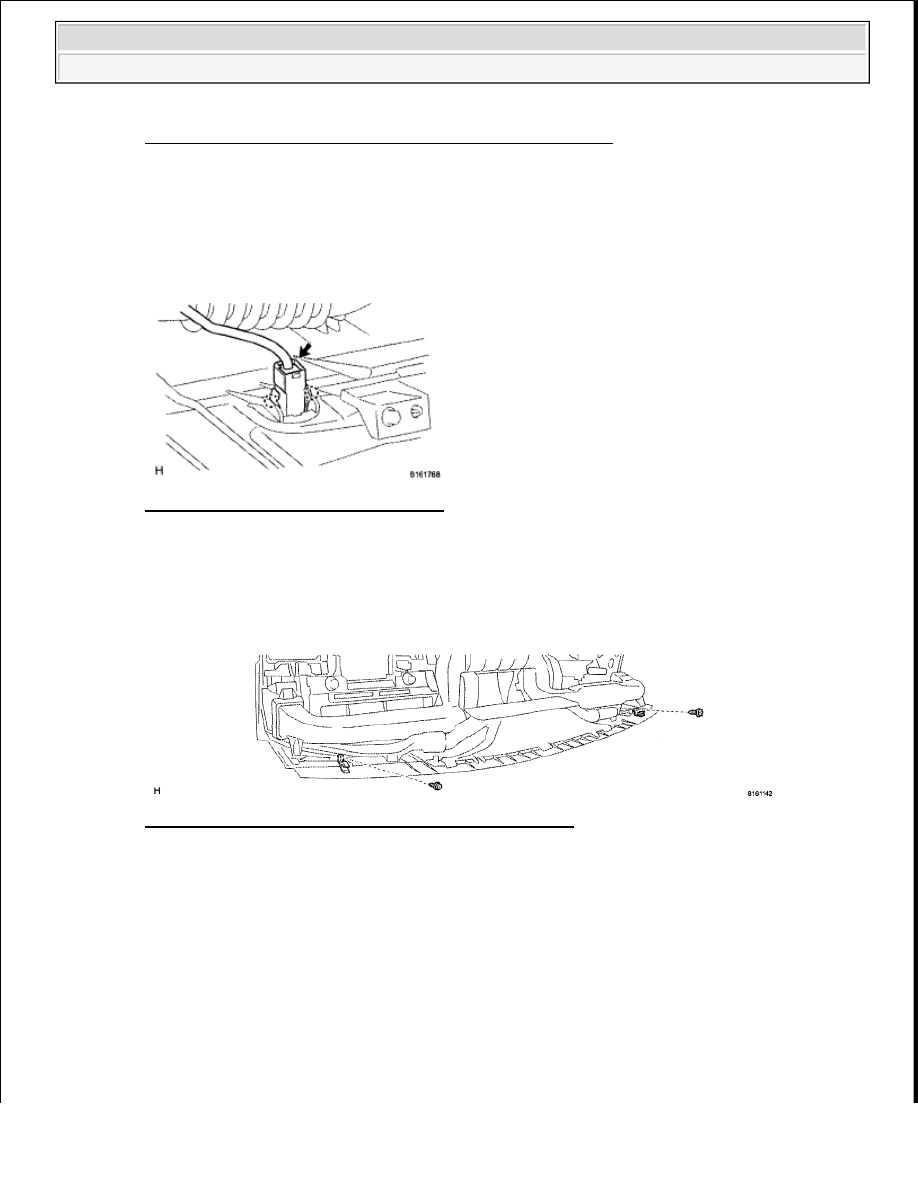
Fig. 114: Identifying No. 3 Instrument Panel Stay And Claws 
Courtesy of TOYOTA MOTOR SALES, U.S.A., INC. 

DISASSEMBLY 

1. REMOVE AUTOMATIC LIGHT CONTROL SENSOR (for Automatic Air Conditioning System) 

a. Disconnect the sensor connector. 

Fig. 115: Identifying Sensor Connector 
Courtesy of TOYOTA MOTOR SALES, U.S.A., INC. 

b. Detach the 2 claws and remove the sensor.  

2. REMOVE NO. 1 INSTRUMENT PANEL PIN 

a. Remove the 2 screws and 2 pins. 

Fig. 116: Identifying No. 1 Instrument Panel Pin Screws 
Courtesy of TOYOTA MOTOR SALES, U.S.A., INC. 

3. REMOVE NO. 1 HEATER TO REGISTER DUCT WITH NO. 2 HEATER TO REGISTER DUCT 

a. Remove the 5 screws and duct. 


2009 Toyota Tundra 

2009 ACCESSORIES AND EQUIPMENT Instrument Panel - Tundra


Fig. 117: Identifying Register Duct Screws 
Courtesy of TOYOTA MOTOR SALES, U.S.A., INC. 

4. REMOVE NO. 1 SIDE DEFROSTER NOZZLE DUCT 

a. Remove the 2 screws. 

Fig. 118: Identifying No. 1 Side Defroster Nozzle Duct Screws And Claws 
Courtesy of TOYOTA MOTOR SALES, U.S.A., INC. 

b. Detach the claw and remove the duct.  

5. REMOVE NO. 4 INSTRUMENT PANEL REGISTER ASSEMBLY 

a. Remove the 3 screws and register. 

Fig. 119: Identifying No. 4 Instrument Panel Register Screws 


2009 Toyota Tundra 

2009 ACCESSORIES AND EQUIPMENT Instrument Panel - Tundra


Courtesy of TOYOTA MOTOR SALES, U.S.A., INC. 

6. REMOVE NO. 2 SIDE DEFROSTER NOZZLE DUCT 

a. Remove the 2 screws. 

Fig. 120: Identifying No. 2 Side Defroster Nozzle Duct Screws 
Courtesy of TOYOTA MOTOR SALES, U.S.A., INC. 

b. Detach the claw and remove the duct.  

7. REMOVE DEFROSTER NOZZLE ASSEMBLY 

a. Remove the 3 screws and nozzle. 

Fig. 121: Identifying Defroster Nozzle Assembly Screws 
Courtesy of TOYOTA MOTOR SALES, U.S.A., INC. 

8. REMOVE NO. 3 INSTRUMENT PANEL REGISTER ASSEMBLY 

a. Remove the 3 screws and register. 


2009 Toyota Tundra 

2009 ACCESSORIES AND EQUIPMENT Instrument Panel - Tundra


Fig. 122: Identifying No. 3 Instrument Panel Register Screws 
Courtesy of TOYOTA MOTOR SALES, U.S.A., INC. 

9. REMOVE ACCESSORY METER ASSEMBLY 

a. Disconnect the accessory meter connector. 

Fig. 123: Identifying Accessory Meter Connector 
Courtesy of TOYOTA MOTOR SALES, U.S.A., INC. 

b. Remove the 3 screws and accessory meter.  

10. REMOVE NAVIGATION ANTENNA ASSEMBLY (w/ Navigation System) (See REMOVAL )  

11. REMOVE NO. 2 INSTRUMENT PANEL WIRE 

a. Detach the wire from the clamps to remove the wire from the instrument panel. 


2009 Toyota Tundra 

2009 ACCESSORIES AND EQUIPMENT Instrument Panel - Tundra


Content   ..  398  399  400  401   ..