Content .. 2905 2906 2907 2908 ..
Toyota Tundra. Manual - part 2907
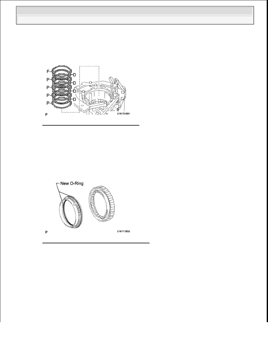
F = Flange
Fig. 557: Identifying Plates, Discs & Flange
Courtesy of TOYOTA MOTOR SALES, U.S.A., INC.
29. INSTALL NO. 3 BRAKE PISTON
a. Coat 2 new O-rings with ATF, and install them to the brake piston.
b. Press the brake piston into the brake cylinder with both hands.
Fig. 558: Identifying No. 3 Brake Piston O-Ring
Courtesy of TOYOTA MOTOR SALES, U.S.A., INC.
c. Using SST and a press, compress the return spring and install the snap ring with a screwdriver.
SST 09380-60010 (09381-06020, 09381-06040, 09381-06060, 09381-06100, 09381-06110)
NOTE:
Before assembling new discs, soak them in ATF for at least 2 hours.
NOTE:
Be careful not to damage the O-rings.
NOTE:
Be sure the end gap of the snap ring is not aligned with the spring
retainer claw.
2009 Toyota Tundra
2009 TRANSMISSION AB60F Automatic Transaxle - Tundra