Toyota Tundra. Manual - part 2892


  Index      Toyota     Toyota Tundra (2007-2010 year) - Service and Repair Manual


Search            copyright infringement  


Content   ..  2890  2891  2892  2893   ..


Toyota Tundra. Manual - part 2892


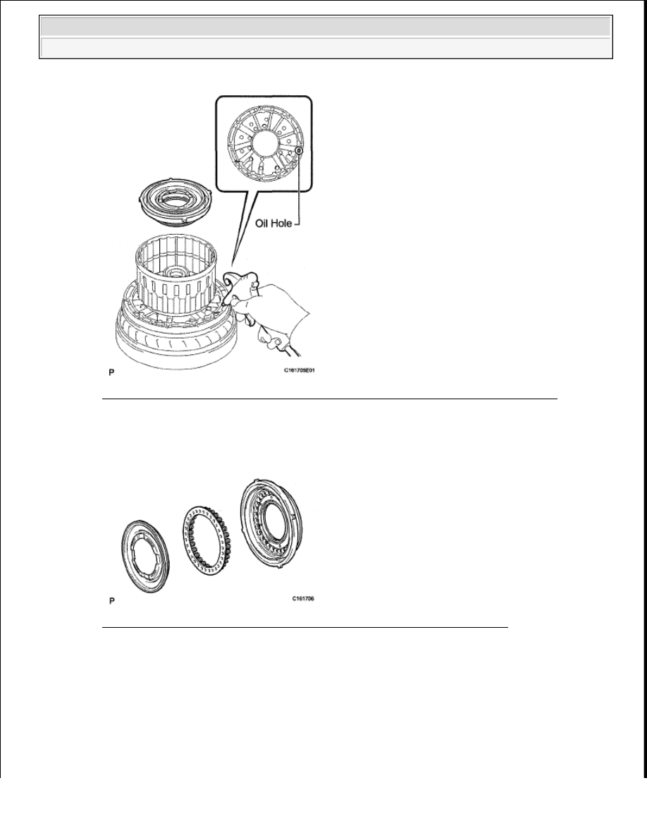
Fig. 441: Identifying Clutch Balancer & Direct Clutch Return Spring Sub-Assembly 
Courtesy of TOYOTA MOTOR SALES, U.S.A., INC. 

e. Remove the No. 2 clutch balancer and direct clutch return spring sub-assembly from the direct 

clutch piston. 

Fig. 442: Identifying No. 2 Clutch Balancer & Direct Clutch Return Spring 
Courtesy of TOYOTA MOTOR SALES, U.S.A., INC. 

f. Remove the 2 O-rings from the direct clutch piston. 


2009 Toyota Tundra 

2009 TRANSMISSION AB60F Automatic Transaxle - Tundra


Fig. 443: Identifying Direct Clutch Piston & O-Rings 
Courtesy of TOYOTA MOTOR SALES, U.S.A., INC. 

58. INSPECT DIRECT CLUTCH RETURN SPRING SUB-ASSEMBLY (See INSPECTION )  

59. REMOVE NO. 3 BRAKE SNAP RING 

a. Using a screwdriver, remove the No. 3 brake snap ring from the transmission case. 

Fig. 444: Using Screwdriver To Remove No. 3 Brake Snap Ring 
Courtesy of TOYOTA MOTOR SALES, U.S.A., INC. 

60. REMOVE NO. 3 BRAKE DISC SET 

a. Remove the 2 flanges, 4 discs and 3 plates from the transmission case. 

Fig. 445: Identifying Flanges, Discs & Plates 
Courtesy of TOYOTA MOTOR SALES, U.S.A., INC. 

61. INSPECT NO. 3 BRAKE DISC (See INSPECTION )  


2009 Toyota Tundra 

2009 TRANSMISSION AB60F Automatic Transaxle - Tundra


62. REMOVE NO. 3 BRAKE PISTON HOLE SNAP RING 

a. Using SST, remove the snap ring. 

SST 09350-30020 (09350-07060)  

Fig. 446: Using SST To Remove No. 3 Brake Piston Hole Snap Ring 
Courtesy of TOYOTA MOTOR SALES, U.S.A., INC. 

63. REMOVE NO. 3 BRAKE CYLINDER WITH NO. 3 BRAKE PISTON AND NO. 3 BRAKE 

PISTON RETURN SPRING SUB-ASSEMBLY 

a. Remove the No. 3 brake cylinder with the No. 3 brake piston and No. 3 brake piston return spring 

from the transmission case. 

Fig. 447: Identifying No. 3 Brake Cylinder With No. 3 Brake Piston & Return Spring 
Courtesy of TOYOTA MOTOR SALES, U.S.A., INC. 

64. REMOVE NO. 3 BRAKE PISTON 

a. Using SST and a press, compress the return spring and remove the snap ring and No. 3 brake piston 

return spring with a screwdriver. 

SST 09380-60010 (09381-06020, 09381-06040, 09381-06060, 09381-06100, 09381-06110)  


2009 Toyota Tundra 

2009 TRANSMISSION AB60F Automatic Transaxle - Tundra


Fig. 448: Compressing Return Spring Using SST & Press 
Courtesy of TOYOTA MOTOR SALES, U.S.A., INC. 

b. Hold the No. 3 brake piston and apply compressed air (392 kPa, 4.0 kgf/cm

2

 , 57 psi) to the No. 3 

brake cylinder to remove the No. 3 brake piston. 

Fig. 449: Applying Compressed Air To No. 3 Brake Cylinder 
Courtesy of TOYOTA MOTOR SALES, U.S.A., INC. 

c. Remove the 2 O-rings from the No. 3 brake piston. 

Fig. 450: Identifying No. 3 Brake Piston O-Rings 
Courtesy of TOYOTA MOTOR SALES, U.S.A., INC. 

65. INSPECT NO. 3 BRAKE PISTON RETURN SPRING SUB-ASSEMBLY (See INSPECTION )  

66. REMOVE 1-WAY CLUTCH ASSEMBLY WITH 1-WAY CLUTCH INNER RACE SUB-

ASSEMBLY 


2009 Toyota Tundra 

2009 TRANSMISSION AB60F Automatic Transaxle - Tundra


Content   ..  2890  2891  2892  2893   ..