Toyota Tundra. Manual - part 2678


  Index      Toyota     Toyota Tundra (2007-2010 year) - Service and Repair Manual


Search            copyright infringement  


Content   ..  2676  2677  2678  2679   ..


Toyota Tundra. Manual - part 2678


REMOVAL 

1. REMOVE FRONT SEAT ASSEMBLY RH 

a. Remove the front seat (see REMOVAL ).  

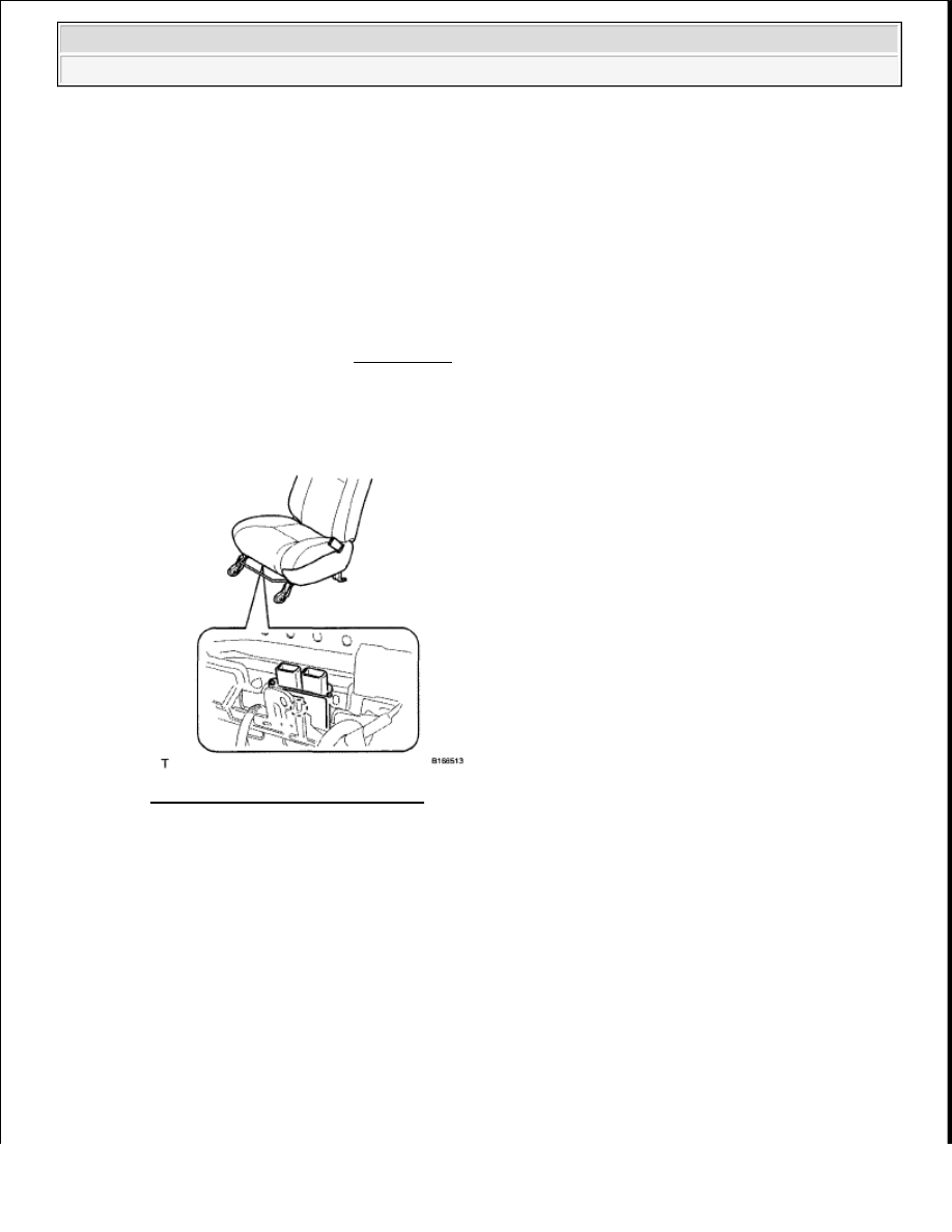
2. REMOVE OCCUPANT CLASSIFICATION ECU 

a. Disconnect the connector.  

b. Detach the claw and remove the ECU from the seat. 

Fig. 383: Identifying Claw & ECU 
Courtesy of TOYOTA MOTOR SALES, U.S.A., INC. 

INSTALLATION 

1. INSTALL OCCUPANT CLASSIFICATION ECU 

a. Check that the ignition switch is OFF.  

b. Check that the cable is disconnected from the battery negative (-) terminal. 

c. Attach the claw and install the occupant classification ECU to the seat. 

For removal and installation procedures of the occupant 
classification ECU, be sure to follow the correct procedure. 

If the airbags have deployed, replace the occupant 
classification ECU on the side in which the collision 
occurred. Replace both if necessary.  

CAUTION: Wait at least 90 seconds after disconnecting the cable from the 

negative (-) battery terminal to prevent airbag and seat belt 
pretensioner activation.


2009 Toyota Tundra 

2009 RESTRAINTS Supplemental Restraint System - Tundra


d. Check that there is no looseness in the installation parts of the ECU. 

Fig. 384: Identifying Claw & ECU 
Courtesy of TOYOTA MOTOR SALES, U.S.A., INC. 

2. INSTALL FRONT SEAT ASSEMBLY RH 

a. Install the front seat (see INSTALLATION ).  

AIRBAG CUT-OFF SWITCH 

COMPONENTS 

NOTE:

If the ECU has been dropped, or there are any cracks, dents or 
other defects in the case, bracket or connector, replace it with a 
new one.  

When installing the ECU, be careful that the SRS wiring does 
not interfere with other parts and that it is not pinched between 
other parts.  


2009 Toyota Tundra 

2009 RESTRAINTS Supplemental Restraint System - Tundra


Fig. 385: Identifying Airbag Cut-Off Switch Replacement Components 
Courtesy of TOYOTA MOTOR SALES, U.S.A., INC. 

REMOVAL 

1. DISCONNECT CABLE FROM NEGATIVE BATTERY TERMINAL 

2. REMOVE INSTRUMENT SIDE PANEL RH (See REMOVAL )  

3. REMOVE LOWER INSTRUMENT PANEL FINISH PANEL SUB-ASSEMBLY RH (See 

CAUTION: Wait at least 90 seconds after disconnecting the cable from the 

negative (-) battery terminal to prevent airbag and seat belt 
pretensioner activation.


2009 Toyota Tundra 

2009 RESTRAINTS Supplemental Restraint System - Tundra


REMOVAL )  

4. REMOVE AIRBAG CUT-OFF SWITCH 

a. Detach the 2 claws to remove the switch.  

INSPECTION 

1. INSPECT AIRBAG CUT-OFF SWITCH 

a. Measure the resistance according to the value(s) in the table below. 

Standard Resistance  

TESTER CONNECTION SPECIFIED CONDITION TABLE 

INSTALLATION 

1. INSTALL AIRBAG CUT-OFF SWITCH 

a. Attach the 2 claws to install the switch. 

Fig. 386: Identifying Airbag Cut-Off Switch Terminals 
Courtesy of TOYOTA MOTOR SALES, U.S.A., INC. 

2. INSTALL LOWER INSTRUMENT PANEL FINISH PANEL SUB-ASSEMBLY (See 

INSTALLATION )  

3. INSTALL INSTRUMENT SIDE PANEL RH (See INSTALLATION )  

4. CONNECT CABLE TO NEGATIVE BATTERY TERMINAL  

5. PERFORM INITIALIZATION 

a. Perform INITIALIZATION . 

Tester Connection Switch Condition Specified Condition

1 (PMC-) - 2 (PMC+)

OFF

400 ohms

1 (PMC-) - 2 (PMC+)

ON

100 ohms


2009 Toyota Tundra 

2009 RESTRAINTS Supplemental Restraint System - Tundra


Content   ..  2676  2677  2678  2679   ..