Toyota Tundra. Manual - part 2260


  Index      Toyota     Toyota Tundra (2007-2010 year) - Service and Repair Manual


Search            copyright infringement  


Content   ..  2258  2259  2260  2261   ..


Toyota Tundra. Manual - part 2260


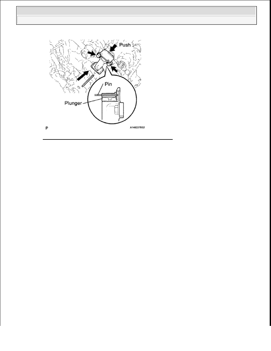
Fig. 421: Locating Rear Engine Mounting Insulator Bolts 
Courtesy of TOYOTA MOTOR SALES, U.S.A., INC. 


2009 Toyota Tundra 

2009 ENGINE Engine Mechanical (3UR-FBE) - Tundra


2009 ENGINE 

Intake (3UR-FE) - Tundra 

INTAKE SYSTEM 

PARTS LOCATION 

Fig. 1: Identifying Intake System Components Location 
Courtesy of TOYOTA MOTOR SALES, U.S.A., INC. 

SYSTEM DIAGRAM 

Fig. 2: Intake System Diagram (1 Of 2) 
Courtesy of TOYOTA MOTOR SALES, U.S.A., INC. 


2009 Toyota Tundra 

2009 ENGINE Intake (3UR-FE) - Tundra


2009 Toyota Tundra 

2009 ENGINE Intake (3UR-FE) - Tundra


Fig. 3: Intake System Diagram (2 Of 2) 
Courtesy of TOYOTA MOTOR SALES, U.S.A., INC. 

ON-VEHICLE INSPECTION 

1. INSPECT INTAKE AIR CONTROL VALVE 

a. Remove the V-bank cover.  

b. Start the engine.  

c. Check that the VSV (for ACIS) is ON (seal) under both of the following conditions below. 

Depressing the accelerator pedal to a throttle valve opening angle of 50° or less.  

Racing the engine to 4700 rpm or more. 

d. Check that the VSV (for ACIS) is OFF (vent) under the following conditions below. 

Releasing the accelerator pedal while under the VSV (for ACIS) OFF condition.  

The engine is idling.  

e. Connect the intelligent tester or Tech stream to the DLC3.  

f. Perform the Active Test, and then check that the actuator rod operates. 

If the result is not as specified, inspect the intake air control valve, vacuum tank and VSV (for 
ACIS) for normal operation. Replace malfunctioning parts as necessary. 

Fig. 4: Inspecting Intake Air Control Valve 
Courtesy of TOYOTA MOTOR SALES, U.S.A., INC. 

g. Install the V-bank cover.  

2. CHECK INTAKE AIR CONTROL VALVE OPERATION 

a. Remove the V-bank cover.  

b. Using a 3-way connector, connect a vacuum gauge to the actuator hose. 

NOTE:

Do not increase the engine speed to 5400 rpm or more.


2009 Toyota Tundra 

2009 ENGINE Intake (3UR-FE) - Tundra


Fig. 5: Connecting Vacuum Gauge To Actuator Hose 
Courtesy of TOYOTA MOTOR SALES, U.S.A., INC. 

c. Start the engine.  

d. While the engine is idling, check that the vacuum gauge indicates 0 kPa (0 mmHg, 0 in.Hg) and the 

rod is at the OFF position  

e. Fully depress the accelerator pedal quickly. Check that the VSV (for ACIS) turns ON and the rod 

moves in the ON direction. 

f. Remove the vacuum gauge, and connect the vacuum hose to the actuator.  

g. Install the V-bank cover.  

3. INSPECT INTAKE AIR CONTROL VALVE 

a. Inspect the diaphragm. 

1. Using a vacuum pump, apply a vacuum of 27 kPa (200 mmHg, 7.85 in.Hg). Check that the 

lever moves. 

If the result is not as specified, replace the intake air surge tank. 

4. CHECK AIR INDUCTION SYSTEM 

HINT: 

The illustration shows the areas that may draw in secondary air, which could lead to idling problems. 

NOTE:

Make sure to fully depress and release the accelerator pedal within 1 
second.


2009 Toyota Tundra 

2009 ENGINE Intake (3UR-FE) - Tundra


Content   ..  2258  2259  2260  2261   ..