Content .. 1805 1806 1807 1808 ..
Toyota Tundra. Manual - part 1807
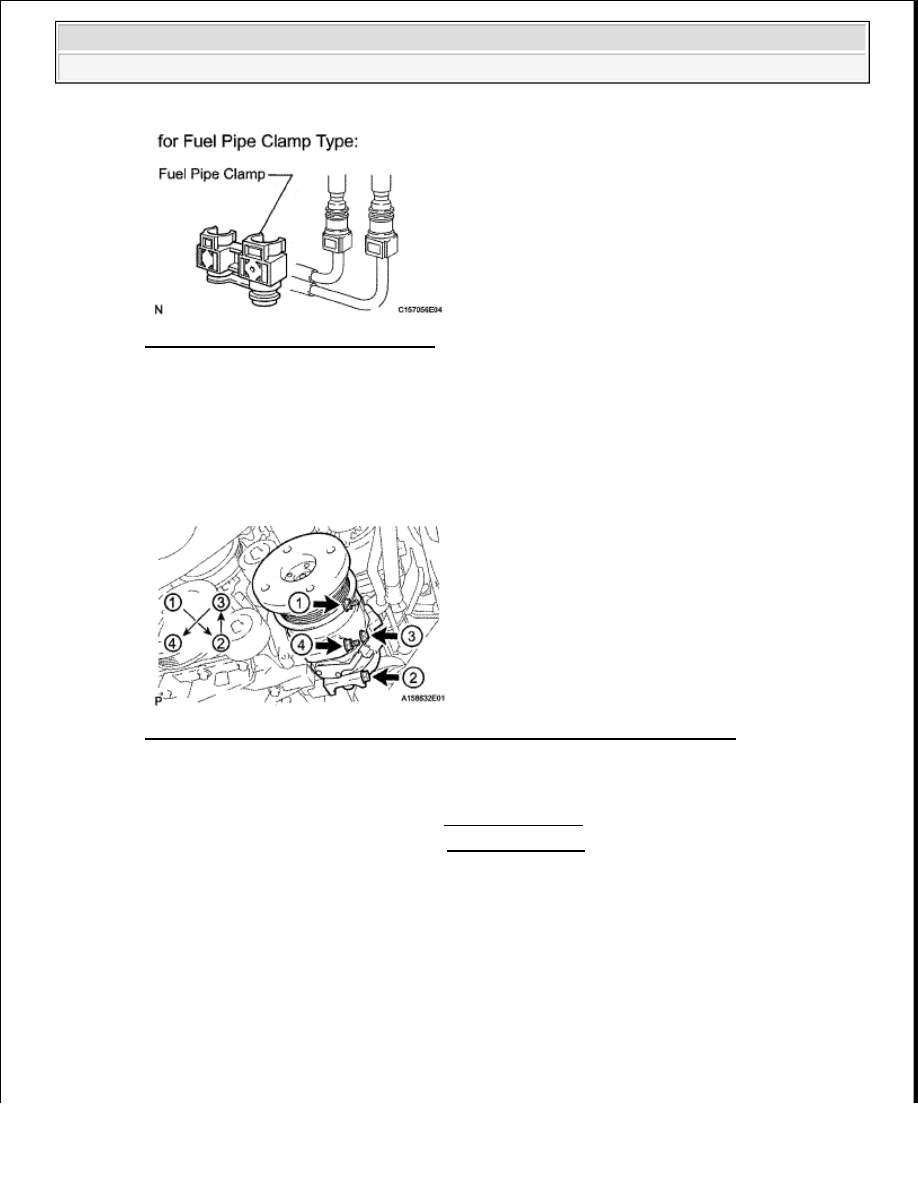
Fig. 211: Identifying Fuel Pipe Clamp
Courtesy of TOYOTA MOTOR SALES, U.S.A., INC.
17
INSTALL COOLER COMPRESSOR
a
Install the cooler compressor with the 2 nuts and 2 bolts in several steps in the sequence shown
below
Torque: 25 N*m (250 kgf*cm, 18 ft.*lbf)
Fig. 212: Identifying Cooler Compressor Nuts And Bolt Tightening Sequence
Courtesy of TOYOTA MOTOR SALES, U.S.A., INC.
b
Connect the cooler compressor connector
18
INSTALL GENERATOR ASSEMBLY (See INSTALLATION )
19
CONNECT VANE PUMP ASSEMBLY (See INSTALLATION )
20
CONNECT HEATER WATER INLET HOSE
a
Install the heater water pipe bracket with the nut
Torque: 8.0 N*m (82 kgf*cm, 71 in.*lbf)
b
Connect the heater water inlet and outlet hose
HINT:
The direction of the hose clamp is indicated below
2009 Toyota Tundra
2009 ENGINE Engine Mechanical (1GR-FE) - Tundra