Toyota Tundra. Manual - part 1448


  Index      Toyota     Toyota Tundra (2007-2010 year) - Service and Repair Manual


Search            copyright infringement  


Content   ..  1446  1447  1448  1449   ..


Toyota Tundra. Manual - part 1448


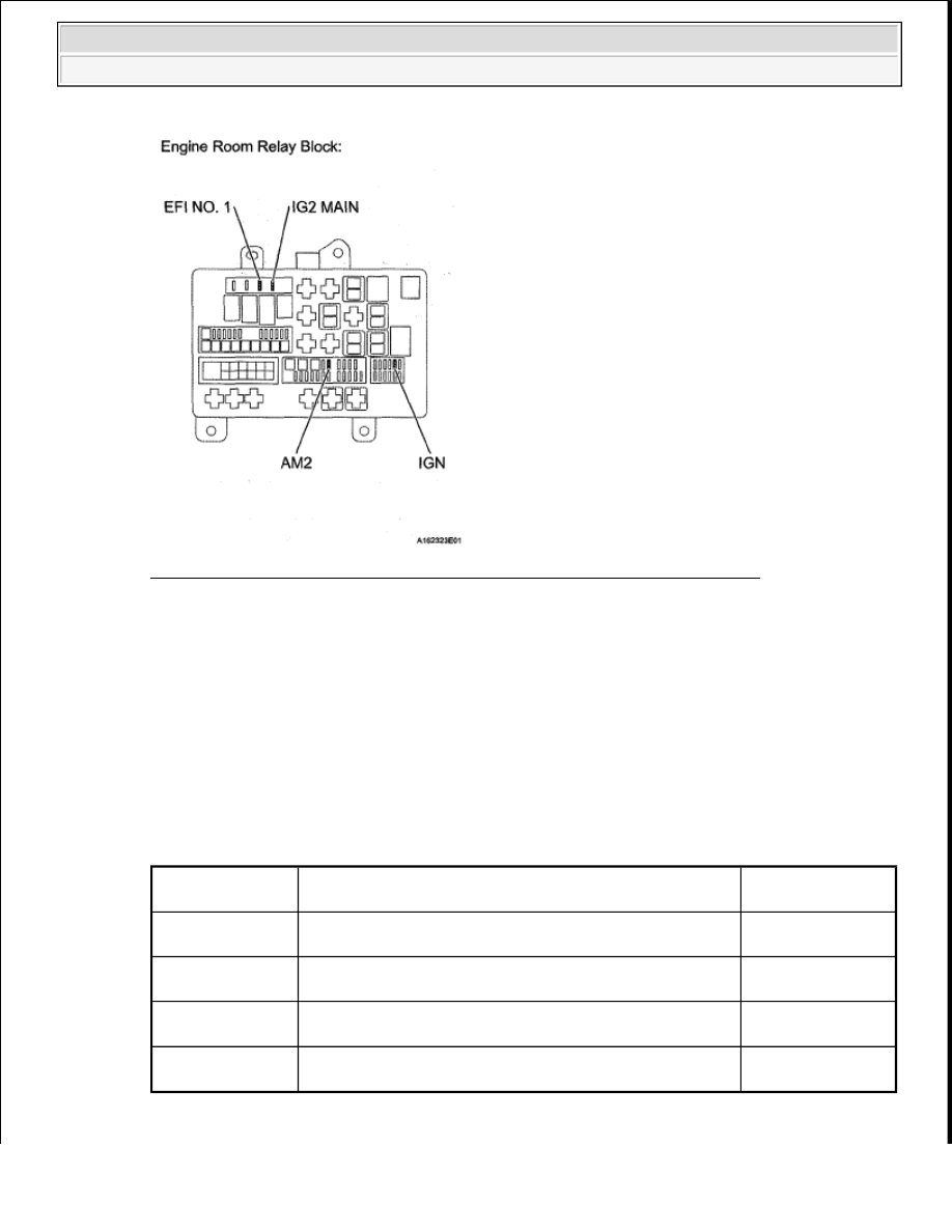
Fig. 278: Identifying AM2 Fuse, IG2 Main Fuse, EFI No. 1 Fuse & IGN Fuse 

NG : CHECK FOR SHORT IN ALL HARNESSES AND CONNECTORS CONNECTED TO 
FUSE AND REPLACE FUSE
  

OK : Go to Next Step  

2. INSPECT RELAY (IG2, EFI) 

a. Remove the integration relay from the engine room relay block.  

b. Measure the resistance according to the value(s) in the table below. 

Standard resistance  

STANDARD RESISTANCE SPECIFICATION 

Tester 

Connection

Condition

Specified 

Condition

1C-1 - 1B-8

When no battery voltage is applied to terminals 1B-6 and 
1B-7

10 kohms or higher

1C-1 - 1B-8

When battery voltage is applied to terminals 1B-6 and 1B-
7

Below 1 ohms

1C-1 - 1B-4

When no battery voltage is applied to terminals 1B-2 and 
1B-3

10 kohms or higher

1C-1 - 1B-4

When battery voltage is applied to terminals 1B-2 and 1B-
3

Below 1 ohms


2008 Toyota Tundra 

2008 ENGINE PERFORMANCE Engine Control System (2UZ-FE) - Tundra


Fig. 279: Identifying Integration Relay 

NG : REPLACE RELAY (See IGNITION RELAY NO. 2 ) 

OK : Go to Next Step  

3. CHECK HARNESS AND CONNECTOR (ECM - BODY GROUND) 

a. Disconnect the D74 ECM connector.  

b. Measure the resistance according to the value(s) in the table below. 

Standard resistance  

STANDARD RESISTANCE SPECIFICATION 

Tester Connection

Condition Specified Condition

D74-81 (E1) - Body ground Always

Below 1 ohms


2008 Toyota Tundra 

2008 ENGINE PERFORMANCE Engine Control System (2UZ-FE) - Tundra


Fig. 280: Identifying D74 ECM Connector 

NG : REPAIR OR REPLACE HARNESS OR CONNECTOR  

OK : Go to Next Step  

4. INSPECT ECM (IGSW VOLTAGE) 

a. Disconnect the A24 and D74 ECM connectors.  

b. Turn the ignition switch to ON.  

c. Measure the voltage according to the value(s) in the table below. 

Standard voltage  

STANDARD VOLTAGE SPECIFICATION 

Fig. 281: Identifying A24 & D74 ECM Connectors 

NG : Go to step 5  

Tester Connection

Switch Condition Specified Condition

A24-28 (IGSW) - D74-81 (E1) Ignition switch ON

11 to 14 V


2008 Toyota Tundra 

2008 ENGINE PERFORMANCE Engine Control System (2UZ-FE) - Tundra


OK : REPLACE ECM (See REMOVAL ) 

5. CHECK HARNESS AND CONNECTOR (RELAY BLOCK - ECM, IGNITION SWITCH, 

BATTERY) 

a. Disconnect the A24 ECM connector.  

b. Disconnect the J9 ignition switch connector.  

c. Disconnect the cable from the battery positive (+) terminal.  

d. Remove the AM2 fuse and integration relay.  

e. Measure the resistance according to the value(s) in the table below. 

Standard resistance  

STANDARD RESISTANCE SPECIFICATION 

Tester Connection

Condition Specified Condition

A24-28 (IGSW) - 1B-8

Always

Below 1 ohms

1B-7 - Body ground

Always

Below 1 ohms

Positive (+) battery cable - 1C-1

Always

Below 1 ohms

Positive (+) battery cable - AM2 fuse terminal 1

Always

Below 1 ohms

J9-5 (AM2) - AM2 fuse terminal 2

Always

Below 1 ohms

J9-6 (IG2) - 1B-6

Always

Below 1 ohms

A24-28 (IGSW) or 1B-8 - Body ground

Always

10 kohms or higher

Positive (+) battery cable or AM2 fuse terminal 1 - Body ground Always

10 kohms or higher

Positive (+) battery cable or 1C-1 - Body ground

Always

10 kohms or higher

J9-5 (AM2) or AM2 fuse terminal 2 - Body ground

Always

10 kohms or higher

J9-6 (IG2) or 1B-6 - Body ground

Always

10 kohms or higher


2008 Toyota Tundra 

2008 ENGINE PERFORMANCE Engine Control System (2UZ-FE) - Tundra


Content   ..  1446  1447  1448  1449   ..