Toyota Tundra. Manual - part 1447


  Index      Toyota     Toyota Tundra (2007-2010 year) - Service and Repair Manual


Search            copyright infringement  


Content   ..  1445  1446  1447  1448   ..


Toyota Tundra. Manual - part 1447


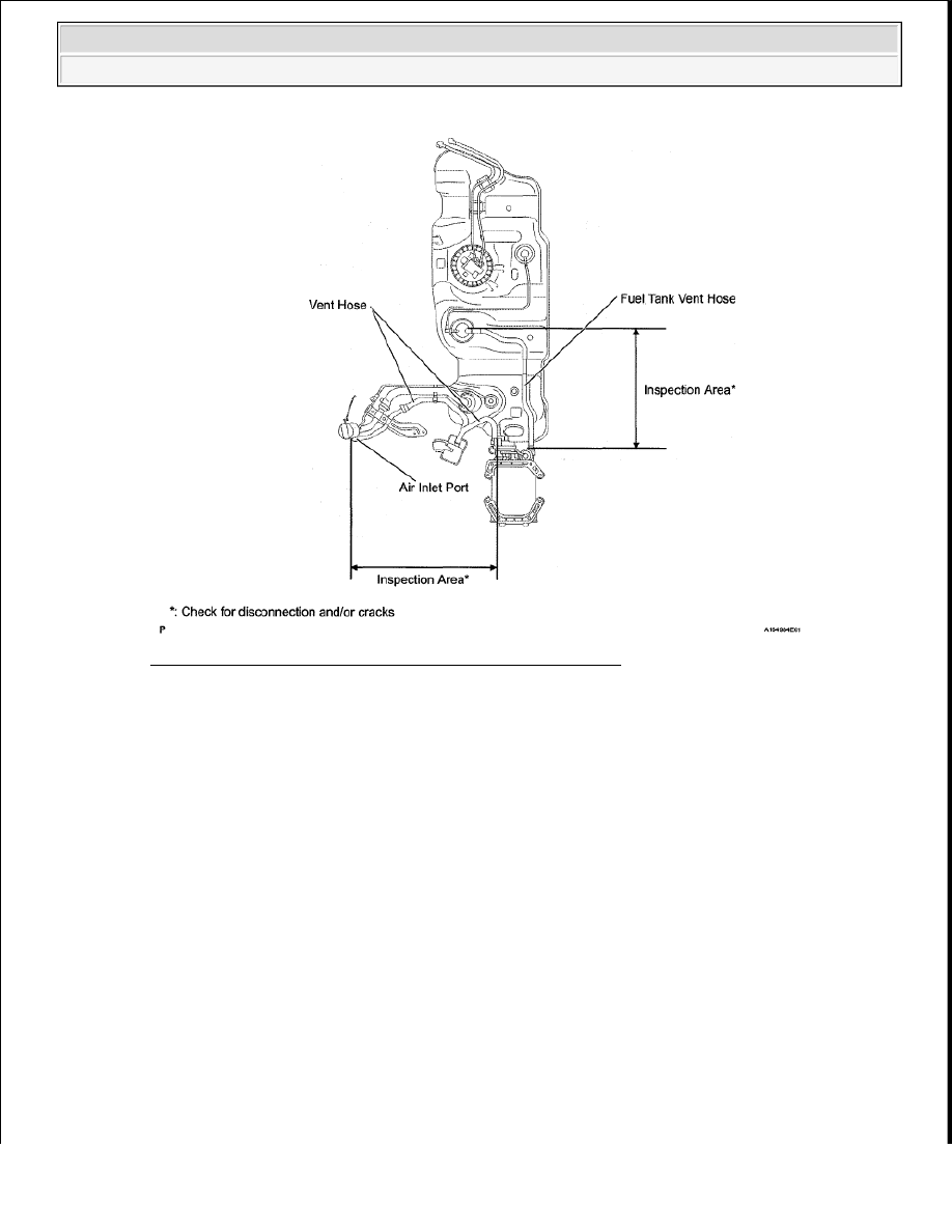
Fig. 275: Identifying Air Inlet Port & Fuel Tank Vent Hose 

NEXT : Go to step 36 

30. REPLACE PURGE VSV 

a. Disconnect the connector and the hoses from the purge VSV.  

b. Replace the purge VSV.  

NEXT : Go to step 36 


2008 Toyota Tundra 

2008 ENGINE PERFORMANCE Engine Control System (2UZ-FE) - Tundra


Fig. 276: Identifying Purge VSV 

31. REPAIR OR REPLACE HARNESS OR CONNECTOR 

NEXT : Go to step 36 

32. REPLACE PURGE LINE (INTAKE MANIFOLD - PURGE VSV) 

NEXT : Go to step 36 

33. INSPECT INTAKE MANIFOLD (EVAP PURGE PORT) 

a. Check that the EVAP purge port of the intake manifold is not clogged. If necessary, replace the 

intake manifold.  

NEXT : Go to step 36 

34. REPLACE ECM 

a. Replace the ECM. (See REMOVAL ).  

NEXT : Go to step 36 

35. REPAIR OR REPLACE PARTS AND COMPONENTS INDICATED BY OUTPUT DTCS 

a. Repair the malfunctioning areas indicated by the DTCs that had been confirmed when the vehicle 

was brought in.  

NEXT : Go to step 36  

36. PERFORM EVAP SYSTEM CHECK (AUTO OPERATION) 

NOTE:

The Evaporative System Check (Automatic Mode) consists of 5 steps 
performed automatically by the Techstream. It takes a maximum of 


2008 Toyota Tundra 

2008 ENGINE PERFORMANCE Engine Control System (2UZ-FE) - Tundra


a. Clear DTCs. (See DTC CHECK/CLEAR ).  

b. Enter the following menus: Powertrain/Engine and ECT/Utility/Evaporative System 

Check/Automatic Mode.  

c. After the Evaporative System Check is completed, check for pending DTCs by entering the 

following menus: Powertrain/Engine and ECT/Trouble Codes/Pending. 

HINT: 

If no pending DTCs are found, the repair has been successfully completed. 

NEXT : COMPLETED  

ECM POWER SOURCE CIRCUIT 

DESCRIPTION 

When the ignition switch is turned to ON, the battery voltage is applied to the IGSW of the ECM. The output 
signal from the MREL terminal of the ECM causes a current to flow to the coil, closing the contacts of the 
integration relay (EFI relay) and supplying power to either terminal +B or +B2 of the ECM. 

WIRING DIAGRAM 

approximately 18 minutes.  

Do not perform the Evaporative System Check when the fuel tank is 
more than 90% full because the cut-off valve may be closed. If the 
cut-off valve is closed, the fuel tank leak check is not possible.  

Do not run the engine in this step.  

When the temperature of the fuel is 35°C (95°F) or more, a large 
amount of vapor forms and any check results become inaccurate. 
When performing an Evaporative System Check, keep the 
temperature below 35°C (95°F).  


2008 Toyota Tundra 

2008 ENGINE PERFORMANCE Engine Control System (2UZ-FE) - Tundra


Fig. 277: ECM Power Source - Wiring Diagram 

INSPECTION PROCEDURE 

1. INSPECT FUSE (AM2, IG2 MAIN, EFI NO. 1 AND IGN) 

a. Remove the AM2 fuse, IG2 MAIN fuse, EFI NO. 1 fuse and IGN fuse from the engine room relay 

block.  

b. Measure the resistance according to the value(s) in the table below. 

Standard resistance  

STANDARD RESISTANCE SPECIFICATION 

Tester Connection Condition Specified Condition
AM2 fuse

Always

Below 1 ohms

IG2 MAIN fuse

Always

Below 1 ohms

EFI NO. 1 fuse

Always

Below 1 ohms

IGN fuse

Always

Below 1 ohms


2008 Toyota Tundra 

2008 ENGINE PERFORMANCE Engine Control System (2UZ-FE) - Tundra


Content   ..  1445  1446  1447  1448   ..