Toyota Tundra. Manual - part 1379


  Index      Toyota     Toyota Tundra (2007-2010 year) - Service and Repair Manual


Search            copyright infringement  


Content   ..  1377  1378  1379  1380   ..


Toyota Tundra. Manual - part 1379


Read freeze frame data using the Techstream. Freeze frame data records the engine condition when 
malfunctions are detected. When troubleshooting, freeze frame data can help determine if the vehicle was 
moving or stationary, if the engine was warmed up or not, if the air-fuel ratio was lean or rich, and other 
data from the time the malfunction occurred.  

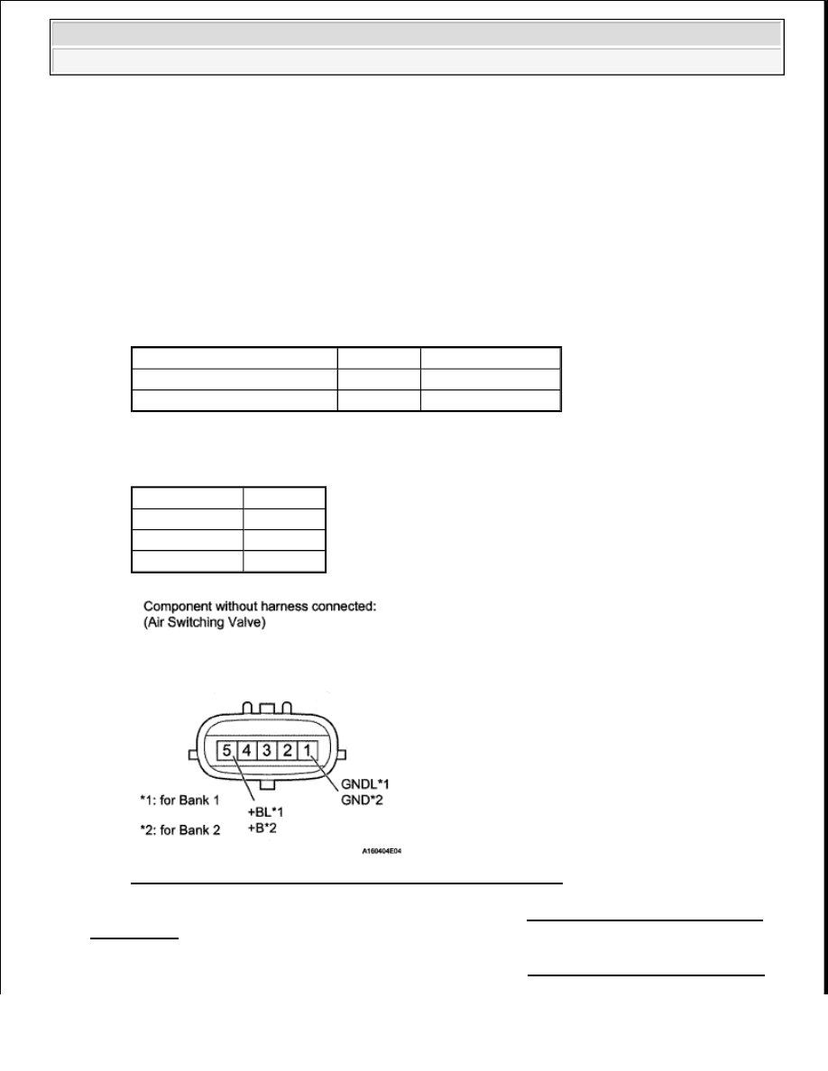
1. INSPECT AIR SWITCHING VALVE ASSEMBLY 

a. Disconnect the D58 or D59 ASV connector.  

b. Measure the resistance according to the value (s) in the table below. 

Standard resistance  

STANDARD RESISTANCE SPECIFICATION 

Result  

RESULT REFERENCE 

Fig. 143: Identifying Air Switching Valve Connector Terminal 

B : REPLACE AIR SWITCHING VALVE ASSEMBLY . (See VACUUM SWITCHING VALVE 
(FOR ACIS)
 ). 

C : REPLACE AIR SWITCHING VALVE ASSEMBLY . (See VACUUM SWITCHING VALVE 

Tester Connection

Condition Specified Condition

D58-S (+BL) - D58-1 (GNDL) 20°C (68°F)

4.5 to 5.5 ohms

D59-5 (+B) - D59-1 (GND)

20°C (68°F)

4.5 to 5.5 ohms

Result

Proceed To

OK

A

NG (for Bank 1)

B

NG (for Bank 2)

C


2008 Toyota Tundra 

2008 ENGINE PERFORMANCE Engine Control System (2UZ-FE) - Tundra


(FOR ACIS) ). 

A : Go To Next Step  

2. CHECK HARNESS AND CONNECTOR (AIR SWITCHING VALVE - BODY GROUND) 

a. Disconnect the D58 or D59 ASV connector.  

b. Measure the resistance according to the value (s) in the table below. 

Standard resistance  

STANDARD RESISTANCE SPECIFICATION 

Fig. 144: Identifying Air Switching Valve Connector Terminal 

NG : REPAIR OR REPLACE HARNESS OR CONNECTOR  

OK : Go To Next Step  

3. CHECK HARNESS AND CONNECTOR (AIR SWITCHING VALVE - AIR INJECTION 

CONTROL DRIVER) 

a. Disconnect the D58 or D59 ASV connector.  

b. Disconnect the D50 or D54 AID connector.  

c. Measure the resistance according to the value (s) in the table below. 

Standard resistance  

STANDARD RESISTANCE SPECIFICATION 

Tester Connection

Condition Specified Condition

D58-1 (GNDL) - Body ground Always

Below 1 ohms

D59-1 (GND) - Body ground

Always

Below 1 ohms


2008 Toyota Tundra 

2008 ENGINE PERFORMANCE Engine Control System (2UZ-FE) - Tundra


Fig. 145: Identifying Air Switching Valve & Air Injection Control Driver Connector 
Terminal
 

NG : REPAIR OR REPLACE HARNESS OR CONNECTOR  

Tester Connection

Condition Specified Condition

D58-5 (+BL) - D50-6 (VV)

Always

Below 1 ohms

D59-5 (+B) - D54-6 (VV2)

Always

Below 1 ohms

D58-5 (+BL) or D50-6 (VV) - Body ground Always

1 kohms or higher

D59-5 (+B) or D54-6 (VV2) - Body ground

Always

1 kohms or higher


2008 Toyota Tundra 

2008 ENGINE PERFORMANCE Engine Control System (2UZ-FE) - Tundra


OK : REPLACE AIR INJECTION CONTROL DRIVER . (SeeVACUUM SWITCHING VALVE 
(FOR ACIS)
 ). 

DTC P0418 SECONDARY AIR INJECTION SYSTEM CONTROL "A" CIRCUIT; DTC P0419 
SECONDARY AIR INJECTION SYSTEM CONTROL "B" CIRCUIT 

DESCRIPTION 

Refer to DTC P0412 . 

DTC DETECTION CONDITION AND TROUBLE AREA 

MONITOR DESCRIPTION 

The Air Injection Control Driver (AID) detects open and short circuits according to the voltages of the air pump 
terminal (VP) and the Air Switching Valve (ASV) terminal (VV), and transmits diagnostic information as a 
signal to the ECM. 

For a short time after cold engine starts, the ECM transmits command signals to the AID to drive the air pump 
and ASV. 

The AID transmits an air pump malfunction signal to the ECM if either of the following conditions is met: 

The voltage at the AID terminal relating to the air pump is low despite the AID receiving command 
signals from the ECM to drive the air pump.  

The voltage at the AID terminal relating to the air pump is high despite the AID receiving no command 
signals from the ECM to drive the air pump.  

DTC 

Code

DTC Detection Condition

Trouble Area

P0418 
P0419

After cold engine starts, all of following conditions met (1 
trip detection logic): 

a. Secondary Air Injection (AIR) system not operating 

(air pump OFF, Air Switching Valve [ASV] OFF)  

b. Diagnostic signal from Air Injection Control Driver 

(AID) 20%  

c. Battery voltage 8 V or higher  

Open in air pump drive 
circuit  

Air pump  

AID  

ECM  

P0418 
P0419

After cold engine starts, all of following conditions met (1 
trip detection logic): 

a. Secondary Air Injection (AIR) system operating (air 

pump ON, Air Switching Valve [ASV] ON)  

b. Diagnostic signal from Air Injection Control Driver 

(AID) 20%  

c. Battery voltage 8 V or higher  

Short between air pump drive 
circuit and body ground  

Air pump  

AID  

ECM  


2008 Toyota Tundra 

2008 ENGINE PERFORMANCE Engine Control System (2UZ-FE) - Tundra


Content   ..  1377  1378  1379  1380   ..