Toyota Tundra. Manual - part 1338


  Index      Toyota     Toyota Tundra (2007-2010 year) - Service and Repair Manual


Search            copyright infringement  


Content   ..  1336  1337  1338  1339   ..


Toyota Tundra. Manual - part 1338


TYPICAL MALFUNCTION THRESHOLDS 

TYPICAL MALFUNCTION THRESHOLDS 

WIRING DIAGRAM 

Refer to DTC P0102 . 

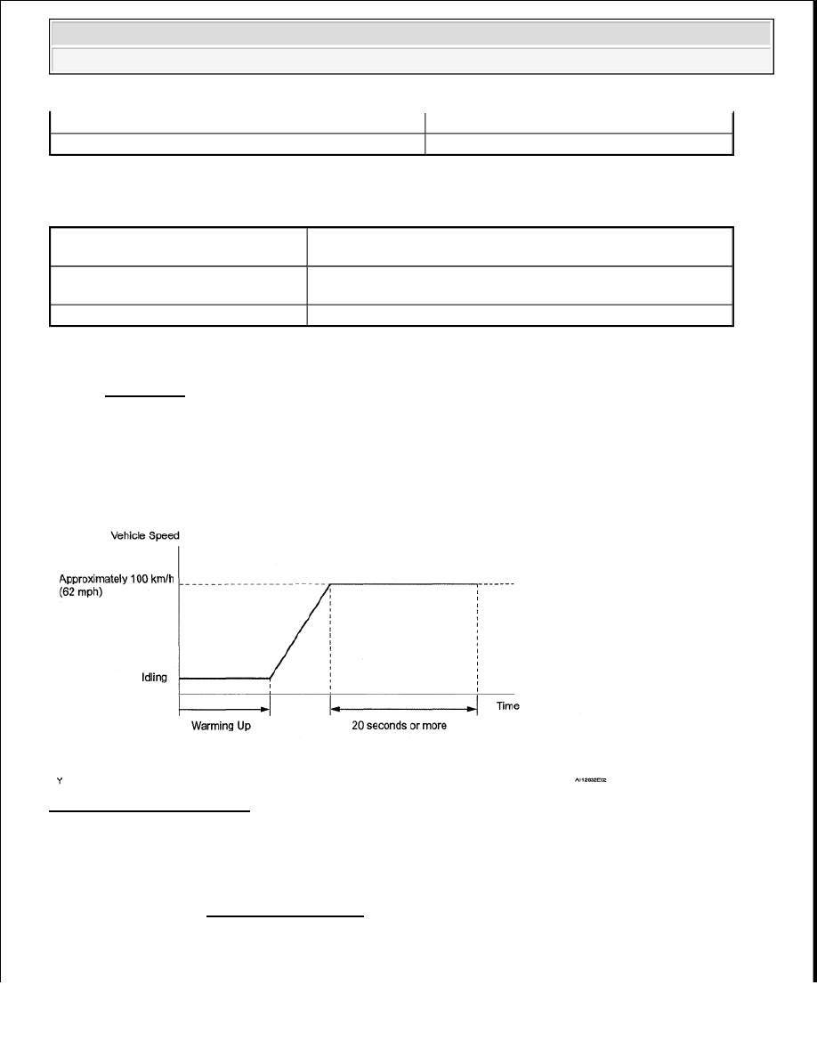
CONFIRMATION DRIVING PATTERN 

HINT: 

Performing this confirmation pattern will activate the mass air flow performance monitor. 

Fig. 55: Vehicle Speed Graph 

1. Connect the Techstream to the DLC3.  

2. Turn the ignition switch to ON.  

3. Turn the Techstream ON.  

4. Clear DTCs. (See DTC CHECK/CLEAR ).  

5. Start the engine, and warm it up until the engine coolant temperature reaches 70°C (158°F) or higher.  

6. Drive the vehicle at approximately 100 km/h (62 mph) for 20 seconds or more.  

EVAP leak detection pump

OK

EVAP vent valve

OK

Both of following conditions 1 and 2 
met

-

1. Averaged engine load value ratio

Less than 0.85, or more than 1.20 (varies with estimated engine 
load)

2. Averaged air-fuel ratio

Less than -15%, or more than 15%


2008 Toyota Tundra 

2008 ENGINE PERFORMANCE Engine Control System (2UZ-FE) - Tundra


7. Enter the following menus: Powertrain/Engine and ECT/Trouble Codes/Pending.  

8. Check if any DTCs (any pending DTCs) are set.  

INSPECTION PROCEDURE 

HINT: 

Read freeze frame data using the Techstream. Freeze frame data records the engine condition when 
malfunctions are detected. When troubleshooting, freeze frame data can help determine if the vehicle was 
moving or stationary, if the engine was warmed up or not, if the air-fuel ratio was lean or rich, and other data 
from the time the malfunction occurred. 

1. CHECK ANY OTHER DTCS OUTPUT (IN ADDITION TO DTC P0101) 

a. Connect the Techstream to the DLC3.  

b. Turn the ignition switch to ON.  

c. Turn the Techstream ON.  

d. Enter the following menus: Powertrain/Engine and ECT/Trouble Codes.  

e. Read DTCs. 

Result  

RESULT REFERENCE 

HINT: 

If any DTCs other than P0101 are output, troubleshoot those DTCs first. 

B : GO TO DTC CHART (See DIAGNOSTIC TROUBLE CODE CHART ) 

A : Go To Next Step  

2. CHECK AIR INDUCTION SYSTEM 

a. Check the air induction system for vacuum leakage. (See ON-VEHICLE INSPECTION ). 

OK: No leakage from air induction system.  

NG : REPAIR OR REPLACE AIR INDUCTION SYSTEM  

OK : Go To Next Step  

3. CHECK PCV HOSE CONNECTIONS 

Result

Proceed To

P0101 is output

A

P0101 and other DTCs are output

B


2008 Toyota Tundra 

2008 ENGINE PERFORMANCE Engine Control System (2UZ-FE) - Tundra


OK: PCV hose is connected correctly and is not damaged.  

NG : REPAIR OR REPLACE PCV HOSE  

OK : REPLACE MASS AIR FLOW METER (See REMOVAL ) 

DTC P0102 MASS OR VOLUME AIR FLOW CIRCUIT LOW INPUT; DTC P0103 MASS OR 
VOLUME AIR FLOW CIRCUIT HIGH INPUT 

DESCRIPTION 

The Mass Air Flow (MAF) meter is a sensor that measures the amount of air flowing through the throttle valve. 

The ECM uses this information to determine the fuel injection time and to provide the appropriate air-fuel ratio. 

Inside the MAF meter, there is a heated platinum wire which is exposed to the flow of intake air. 

By applying a specific electrical current to the wire, the ECM heats it to a given temperature. The flow of 
incoming air cools both the wire and an internal thermistor, affecting their resistance. To maintain a constant 
current value, the ECM varies the voltage applied to these components in the MAF meter. The voltage level is 
proportional to the airflow through the sensor, and the ECM uses it to calculate the intake air volume. 

The circuit is constructed so that the platinum hot wire and the cold film element create a bridge circuit, and the 
power transistor is controlled so that the potentials of A and B remain equal to maintain the predetermined 
temperature. 

HINT: 

When any of these DTCs are set, the ECM enters fail-safe mode. During fail-safe mode, the ignition timing is 
calculated by the ECM, according to the engine RPM and throttle valve position. Fail-safe mode continues until 
a pass condition is detected. 

Fig. 56: Power Transistor Circuit Diagram 


2008 Toyota Tundra 

2008 ENGINE PERFORMANCE Engine Control System (2UZ-FE) - Tundra


DTC DETECTION CONDITION AND TROUBLE AREA 

HINT: 

When any of these DTCs are set, check the air-flow rate by entering the following menus: Powertrain/Engine 
and ECT/Data List/All Data/MAF. 

DATA LIST REFERENCE 

MONITOR DESCRIPTION 

If there is a defect in the MAF meter or an open or short circuit, the voltage level deviates from the normal 
operating range. The ECM interprets this deviation as a malfunction in the MAF meter and sets a DTC. 

Example: 

When the sensor output voltage remains less than 0.2 V, or higher than 4.9 V, for more than 3 seconds, the 
ECM sets a DTC. 

If the malfunction is not repaired successfully, a DTC is set 3 seconds after the engine is next started. 

MONITOR STRATEGY 

MONITOR STRATEGY 

DTC 

Code

DTC Detection Condition

Trouble Area

P0102

MAF meter voltage less than 0.2 V for 3 seconds (1 trip 
detection logic)

Open or short in MAF meter 
circuit  

MAF meter  

ECM  

P0103

MAF meter voltage more than 4.9 V for 3 seconds (1 trip 
detection logic)

Open or short in MAF meter 
circuit  

MAF meter  

ECM  

Mass Air Flow Rate (g/sec.)

Malfunction

Approximately 0.0

Open in Mass Air Flow (MAF) meter power source circuit  

Open or short in VG circuit  

271.0 or more

Open in E2G circuit

Related DTCs

P0102: MAF meter range check (Low voltage) 
P0103: MAF meter range check (High voltage)

Required Sensors/Components 
(Main)

MAF meter

Required Sensors/Components 
(Related)

Crankshaft position sensor


2008 Toyota Tundra 

2008 ENGINE PERFORMANCE Engine Control System (2UZ-FE) - Tundra


Content   ..  1336  1337  1338  1339   ..