Toyota Tundra. Manual - part 1309


  Index      Toyota     Toyota Tundra (2007-2010 year) - Service and Repair Manual


Search            copyright infringement  


Content   ..  1307  1308  1309  1310   ..


Toyota Tundra. Manual - part 1309


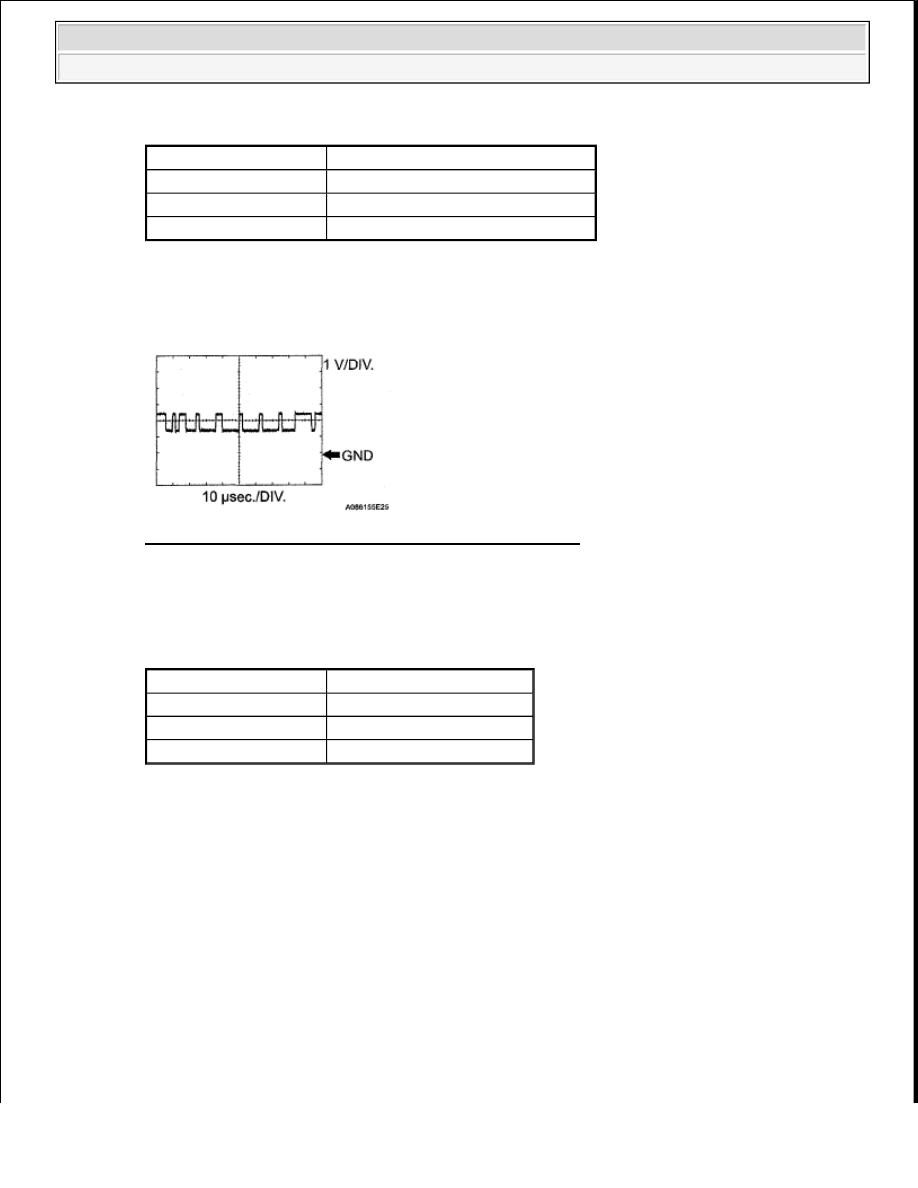
CAN COMMUNICATION SIGNAL - WAVEFORM REFERENCE 

HINT: 

The waveform varies depending on the CAN communication signal. 

Fig. 28: CAN Communication Signal - Waveform Graph 

o. WAVEFORM 14: 

Camshaft position sensor  

CAMSHAFT POSITION SENSOR - WAVEFORM REFERENCE 

HINT: 

The wavelength becomes shorter as engine RPM increases.  

*1: 720°  

*2: 180°  

*3: 120°  

*4: 60° 

Item

Content

Terminal No. (Symbols)

Between CANL and E1

Tool Setting

1 V/DIV., 10 µsec./DIV.

Condition

Engine stops and ignition switch ON

Item

Content

Terminal No. (Symbols)

Between G2 and G2-

Tool Setting

2 V/DIV., 200 msec./DIV.

Condition

Idle after engine warmed up


2008 Toyota Tundra 

2008 ENGINE PERFORMANCE Engine Control System (2UZ-FE) - Tundra


Fig. 29: Camshaft Position Sensor - Waveform Graph 

p. WAVEFORM 15: 

Terminal Dl of air injection control driver  

TERMINAL DL OF AIR INJECTION CONTROL DRIVER - WAVEFORM REFERENCE 

HINT: 

The wavelength changes when the air injection control driver detects malfunctions in the air 
injection system. (See DTC P0412 SECONDARY AIR INJECTION SYSTEM SWITCHING 
VALVE "A" CIRCUIT; DTC P0415 SECONDARY AIR INJECTION SYSTEM 
SWITCHING VALVE "B" CIRCUIT
 ). 

Fig. 30: Terminal DL Of Air Injection Control Driver - Waveform Graph 

DIAGNOSIS SYSTEM 

1. DESCRIPTION 

When troubleshooting OBD II (On-Board Diagnostics) vehicles, the Techstream (complying with SAE 
J1987) must be connected to the DLC3 (Data Link Connector 3) of the vehicle. Various data in the 

Item

Content

Terminal No. (Symbols)

Between AIDI or AID2 and E1

Tool Setting

5 V/DIV., 20 to 40 msec./DIV.

Condition

Performing system check using Techstream (air injection check)


2008 Toyota Tundra 

2008 ENGINE PERFORMANCE Engine Control System (2UZ-FE) - Tundra


vehicle's ECM (Engine Control Module) can be then read. 

OBD II regulations require that the vehicle's on-board computer illuminate the MIL (Malfunction 
Indicator Lamp) on the instrument panel when the computer detects a malfunction in: 

a. The emission control systems components.  

b. The powertrain control components (which affect vehicle emissions).  

c. The computer itself. 

Fig. 31: Identifying Malfunction Indicator Lamp 

In addition, the applicable DTCs prescribed by SAE J2012 are recorded in the ECM memory. If the 
malfunction does not recur in 3 consecutive trips, the MIL turns off automatically but the DTCs remain 
recorded in the ECM memory. 

To check the DTCs, connect the Techstream to the DLC3. The Techstream displays DTCs, freeze frame 
data, and a variety of the engine data. The DTCs and freeze frame data can be erased with the 
Techstream. In order to enhance OBD function on vehicles and develop the Off-Board diagnosis system, 
Controller Area Network (CAN) communication is used in this system. CAN is a network which uses a 
pair of data transmission lines spanning multiple computers and sensors. It allows for high speed 
communications between the systems and simplification of the wire harness connections. 

2. NORMAL MODE AND CHECK MODE 

The diagnosis system operates in normal mode during normal vehicle use. In normal mode, 2 trip 
detection logic is used to ensure accurate detection of malfunctions. Check mode is also available as an 
option for technicians. In check mode, 1 trip detection logic is used for simulating malfunction symptoms 
and increasing the system's ability to detect malfunctions, including intermittent problems (Techstream 
only). 

3. TRIP DETECTION LOGIC 

When a malfunction is first detected, the malfunction is temporarily stored in the ECM memory (1st trip). 
If the same malfunction is detected during the next subsequent drive cycle, the MIL is illuminated (2nd 
trip). 

4. FREEZE FRAME DATA 

The ECM records vehicle and driving condition information as freeze frame data the moment a DTC is 


2008 Toyota Tundra 

2008 ENGINE PERFORMANCE Engine Control System (2UZ-FE) - Tundra


stored. When troubleshooting, freeze frame data can be helpful in determining whether the vehicle was 
running or stopped, whether the engine was warmed up or not, whether the air-fuel ratio was lean or rich, 
as well as other data recorded at the time of a malfunction. 

5. BATTERY VOLTAGE 

Standard voltage:  

11 to 14 V  

If voltage is below 11V, replace or recharge the battery before proceeding. 

6. MIL (Malfunction Indicator Lamp) 

a. The MIL is illuminated when the ignition switch is first turned ON (the engine is not running).  

b. The MIL should turn OFF when the engine is started. If the MIL remains illuminated, the diagnosis 

system has detected a malfunction or abnormality in the system. 

HINT: 

If the MIL is not illuminated when the ignition switch is first turned ON, check the MIL circuit. 
(See MIL CIRCUIT ). 

7. ALL READINESS 

HINT: 

With "ALL READINESS" you can check whether or not the DTC judgment has been completed by 
using the Techstream.  

You should check "ALL READINESS" after simulating malfunction symptoms or for validation 
after finishing repairs.  

a. Connect the Techstream to the DLC3.  

b. Turn the ignition switch to ON.  

c. Turn the Techstream ON.  

d. Clear the DTCs.  

e. Perform the DTC judgment driving pattern to run the DTC judgment.  

f. Enter the following menus: Powertrain/Engine/Utility/All Readiness.  

g. Input the DTCs to be confirmed.  

h. Check the DTC judgment result. 

DTC CHART 

Display Item

Description

NORMAL

DTC judgment completed  

System normal  


2008 Toyota Tundra 

2008 ENGINE PERFORMANCE Engine Control System (2UZ-FE) - Tundra


Content   ..  1307  1308  1309  1310   ..