Toyota Tundra. Manual - part 1292


  Index      Toyota     Toyota Tundra (2007-2010 year) - Service and Repair Manual


Search            copyright infringement  


Content   ..  1290  1291  1292  1293   ..


Toyota Tundra. Manual - part 1292


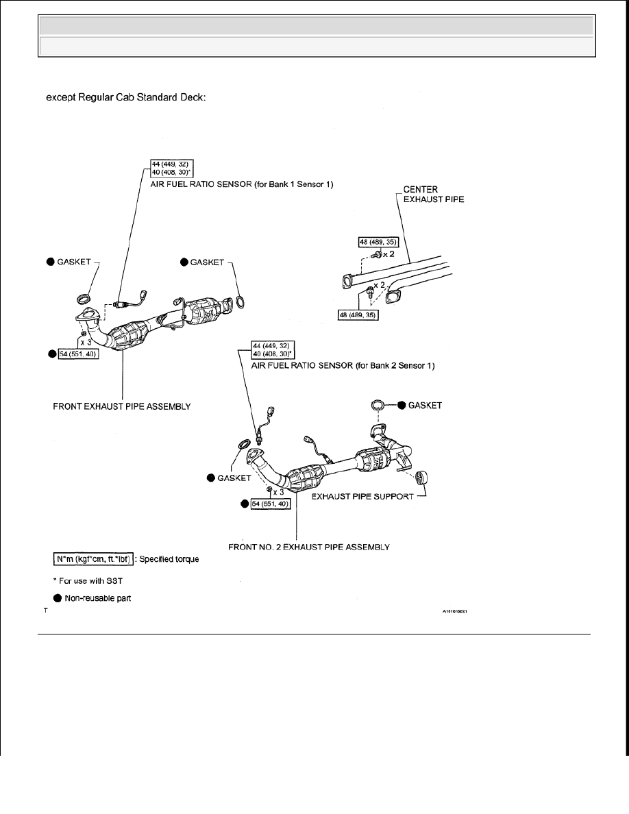
Fig. 365: Identifying Air Fuel Ratio Sensor Replacement Components With Torque Specification (2 Of 2) 

ON-VEHICLE INSPECTION 

1. INSPECT AIR FUEL RATIO SENSOR 

a. Disconnect the 2 sensor connectors.  

b. Measure the heater resistance according to the value (s) in the table below. 


2008 Toyota Tundra 

2008 ENGINE PERFORMANCE Engine Control System (1GR-FE) - Tundra


Standard resistance (for Bank 1 sensor 1)  

TESTER CONNECTION SPECIFIED CONDITION 

Standard resistance (for Bank 2 sensor 1)  

TESTER CONNECTION SPECIFIED CONDITION 

If the result is not as specified, replace the air fuel ratio sensor. 

c. Connect the 2 sensor connectors. 

Fig. 366: Identifying Air Fuel Ratio Sensor Connector Terminals 

2. INSPECT AIR-FUEL RATIO COMPENSATION SYSTEM 

HINT: 

Malfunctioning areas can be identified by performing the Control the Injection Volume for A/F sensor 
function provided in the Active Test. The Control the Injection Volume for A/F sensor function can help 
to determine whether the Air-Fuel Ratio (A/F) sensor, Heated Oxygen (HO2) sensor and other potential 
trouble areas are malfunctioning. 

The following instructions describe how to conduct the Control the Injection Volume for A/F sensor 
operation using the Techstream. 

1. Connect the Techstream to the DLC3.  

Tester Connection Condition Specified Condition

1 (HA1A) - 2 (+B) 20°C (68°F)

1.8 to 3.4 ohms

Tester Connection Condition Specified Condition

1 (HA2A) - 2 (+B) 20°C (68°F)

1.8 to 3.4 ohms


2008 Toyota Tundra 

2008 ENGINE PERFORMANCE Engine Control System (1GR-FE) - Tundra


2. Start the engine and turn the Techstream main switch ON.  

3. Warm up the engine at an engine speed of 2500 RPM for approximately 90 seconds.  

4. Enter the following menus: Engine and ECT/Active Test/Control the Injection Volume for A/F 

sensor.  

5. Perform the Active Test operation with the engine in an idling condition (press the RIGHT or 

LEFT button to change the fuel injection volume).  

6. Monitor the output voltages of the A/F and HO2 sensors (AFS B1 S1 and O2S B1 S2 or AFS B2 

S1 and O2S B2 S2) displayed on the Techstream. 

HINT: 

The Control the Injection Volume for A/F sensor operation lowers the fuel injection volume 
by 12.5% or increases the injection volume by 25%.  

Each sensor reacts in accordance with increases and decreases in the fuel injection volume.  

VOLTAGE REFERENCE 

VOLTAGE REFERENCE 

Tester Display (Sensor)

Injection Volume Status

Voltage

AFS B1 S1 or AFS B2 S1 (A/F)

+25%

Rich

Less than 3.0 V

AFS B1 S1 or AFS B2 S1 (A/F)

-12.5%

Lean More than 3.35 V

O2S B1 S2 or O2S B2 S2 (HO2)

+25%

Rich More than 0.55 V

O2S B1 S2 or O2S B2 S2 (HO2)

-12.5%

Lean

Less than 0.4 V

NOTE:

The Air-Fuel Ratio (A/F) sensor has an output delay of a few seconds 
and the Heated Oxygen (HO2) sensor has a maximum output delay of 
approximately 20 seconds.

Case

A/F Sensor (Sensor 1) 

Output Voltage

HO2 Sensor (Sensor 2) 

Output Voltage

Main Suspected Trouble 

Area

1

-

2

A/F sensor  

A/F sensor heater  

A/F sensor circuit  

3

HO2 sensor  

HO2 sensor heater  

HO2 sensor circuit  

Injector  

Fuel pressure  


2008 Toyota Tundra 

2008 ENGINE PERFORMANCE Engine Control System (1GR-FE) - Tundra


Following the Control the Injection Volume for A/F sensor procedure enables technicians to 
check and graph the voltage outputs of both the A/F and HO2 sensors.  

To display the graph, enter the following menus: Powertrain/Engine and ECT/Active 
Test/Control the Injection Volume for A/F Sensor/A/F Control System/AFS B1 S1 and O2S 
B1 S2 or AFS B2 S1 and O2S B2 S2.  

REMOVAL 

1. DISCONNECT CABLE FROM NEGATIVE BATTERY TERMINAL 

2. REMOVE FRONT NO. 3 EXHAUST PIPE SUB-ASSEMBLY (for Regular Cab Standard Deck) 

a. Remove the 4 bolts and 2 nuts.  

b. Disconnect the exhaust pipe from the exhaust pipe support, and remove the 2 gaskets.  

3. REMOVE FRONT NO. 2 EXHAUST PIPE ASSEMBLY (for Regular Cab Standard Deck) 

a. Disconnect the air fuel ratio sensor connector.  

b. Disconnect the heated oxygen sensor connector.  

c. Remove the 3 nuts, exhaust pipe and gasket.  

4. REMOVE FRONT NO. 2 EXHAUST PIPE ASSEMBLY (except Regular Cab Standard Deck) 

a. Disconnect the air fuel ratio sensor connector.  

b. Disconnect the heated oxygen sensor connector.  

c. Remove the 3 nuts, 2 bolts, exhaust pipe and gasket.  

5. REMOVE FRONT EXHAUST PIPE ASSEMBLY 

a. Disconnect the air fuel ratio sensor connector.  

b. Disconnect the heated oxygen sensor connector and 2 clamps.  

c. Remove the 2 bolts.  

d. Remove the 3 nuts, exhaust pipe and 2 gaskets.  

6. REMOVE AIR FUEL RATIO SENSOR (for Bank 1 Sensor 1) 

a. Using SST, remove the sensor. 

4

Gas leakage from 
exhaust system (Air-
fuel ratio extremely 
rich or lean)  

NOTE:

Some systems need to be initialized after the cable is reconnected 
(see INITIALIZATION ).  

After the ignition switch is turned OFF, the navigation system 
requires approximately 90 seconds to record various types of 
memory and settings. As a result, after turning the ignition switch 
OFF, wait 90 seconds or more before disconnecting the cable from 
the negative (-) battery terminal.  


2008 Toyota Tundra 

2008 ENGINE PERFORMANCE Engine Control System (1GR-FE) - Tundra


Content   ..  1290  1291  1292  1293   ..