Toyota Tundra. Manual - part 1067


  Index      Toyota     Toyota Tundra (2007-2010 year) - Service and Repair Manual


Search            copyright infringement  


Content   ..  1065  1066  1067  1068   ..


Toyota Tundra. Manual - part 1067


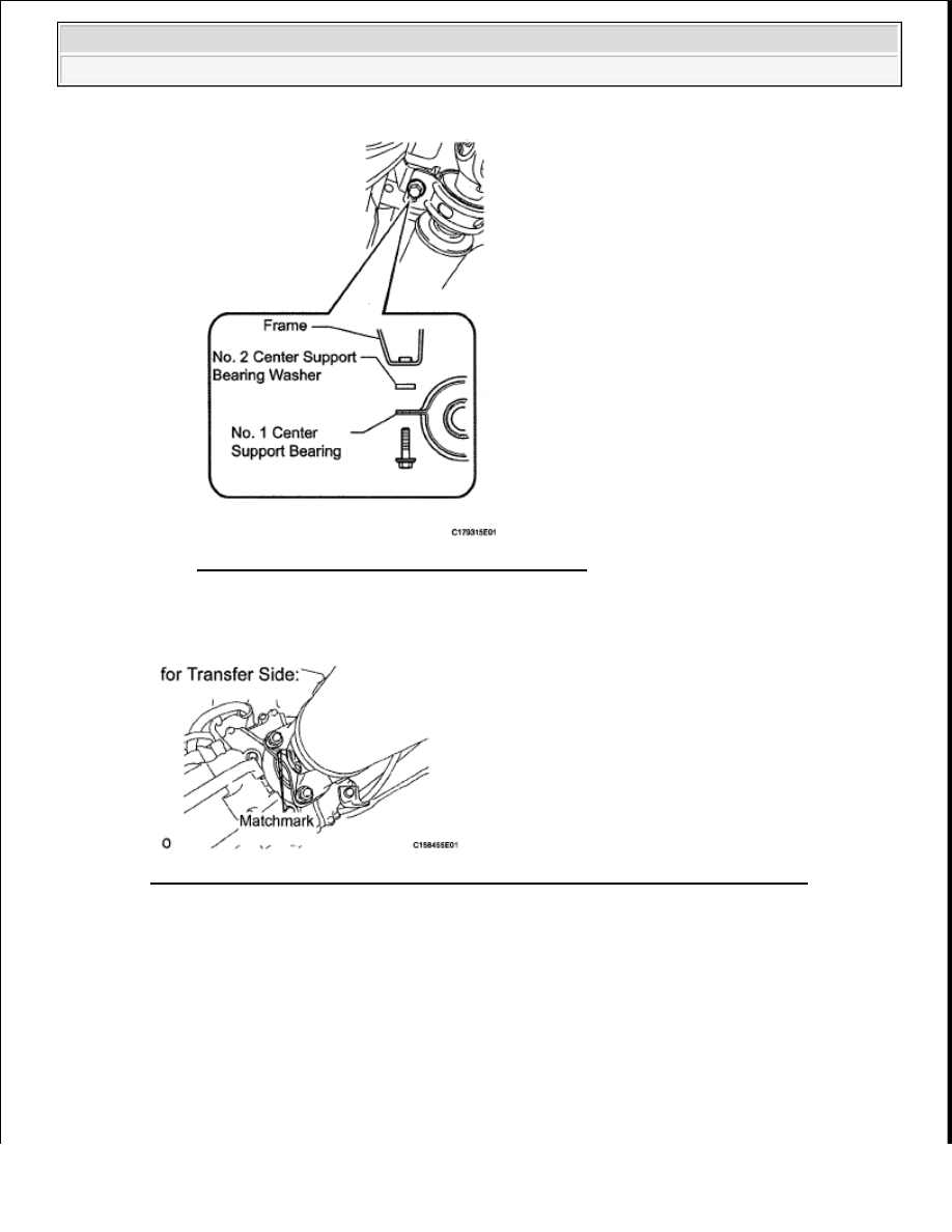
Fig. 122: Locating Crossmember Mounting Bolts 
Courtesy of TOYOTA MOTOR SALES, U.S.A., INC. 

c. Align the matchmarks on the flange yoke and transfer flange. 

Fig. 123: Identifying Matchmarks On Propeller Shaft Flange And Transfer Flange 
Courtesy of TOYOTA MOTOR SALES, U.S.A., INC. 

d. Install the propeller shaft to the transfer side with the 4 nuts. 

Torque: 70 N*m (714 kgf*cm, 52 ft.*lbf)  

e. Align the matchmarks on the flange yoke and differential flange. 


2009 Toyota Tundra 

2009 DRIVELINE/AXLES Propeller Shaft - Tundra


Fig. 124: Identifying Matchmarks On Propeller Shaft Flange And Differential Flange 
Courtesy of TOYOTA MOTOR SALES, U.S.A., INC. 

f. Install the propeller shaft to the differential side with the 4 bolts and 4 nuts. 

Torque: 70 N*m (714 kgf*cm, 52 ft.*lbf)  

4. TIGHTEN PROPELLER WITH CENTER BEARING SHAFT ASSEMBLY (for 3 Joint Type) 

a. With the vehicle empty and all 4 tires supported by a lift, or with the vehicle suspension in the full 

rebound position, adjust the center bearing so that dimension A (the distance from the front surface 
of the center bearing housing to the back surface of the intermediate shaft) is as shown in the chart 
below. 

HINT: 

Measure dimension A (the distance from the front surface of the center bearing housing to the back 
surface of the intermediate shaft) at 3 places and make adjustments so that the measured 
dimensions are equal. 

Fig. 125: Identifying Intermediate Shaft Dimension 
Courtesy of TOYOTA MOTOR SALES, U.S.A., INC. 


2009 Toyota Tundra 

2009 DRIVELINE/AXLES Propeller Shaft - Tundra


Standard dimension A  

VEHICLE MODEL SPECIFICATION 

b. Check that the center line of the bracket is at right angles to the shaft axial direction. 

Fig. 126: Checking Center Line Of Bracket 
Courtesy of TOYOTA MOTOR SALES, U.S.A., INC. 

c. Tighten the 2 mounting bolts. 

Torque: 40 N*m (410 kgf*cm, 30 ft.*lbf)  

5. INSPECT PROPELLER SHAFT JOINT ANGLE (for 3 Joint Type) 

a. Measure the No. 1 joint angle. 

1. Using SST, measure and record the angle of the intermediate shaft (C). 

SST 09370-50010  

Vehicle 

model

Vehicle condition

Dimension A

All model

Tires supported and vehicle empty (When using drive-on type 
lift)

26.0 mm (1.024 

in.)

Full rebound position (When using 2 post lift)

26.0 mm (1.024 

in.)

NOTE:

Perform the inspection on a level surface.  

Perform the inspection with the vehicle empty.  

Perform the inspection with all wheels on the ground. 


2009 Toyota Tundra 

2009 DRIVELINE/AXLES Propeller Shaft - Tundra


Fig. 127: Identifying Intermediate Shaft (C) 
Courtesy of TOYOTA MOTOR SALES, U.S.A., INC. 

2. Subtract the angle of the transfer flange (A) measured before installing the propeller shaft 

from the angle of the intermediate shaft (C) to calculate the No. 1 joint angle. 

No. 1 joint angle:  

Angle of intermediate shaft (C) - Angle of transfer flange (A)  

Fig. 128: Identifying No. 1 Joint Angle 
Courtesy of TOYOTA MOTOR SALES, U.S.A., INC. 

Measured Value (Reference)  

INTERMEDIATE SHAFT ANGLE MEASURED VALUE REFERENCE 

HINT: 

Using the following chart, check if the calculated No. 1 joint angle is within the 

Intermediate Shaft Angle 

Measured Value (C)

transfer Flange Angle 

Measured Value (A)

No. 1 Joint Angle 

(Calculated Value) (C) - (A)

2°30' (2.50°)

3°45' (3.75°)

-1°15' (-1.25°)


2009 Toyota Tundra 

2009 DRIVELINE/AXLES Propeller Shaft - Tundra


Content   ..  1065  1066  1067  1068   ..