Suzuki Grand Vitara JB416 / JB420 / JB419. Manual - part 306


  Index      Suzuki     Suzuki Grand Vitara JB416 / JB420 / JB419 - service repair manual 2007 year


Search            


Content   ..  304  305  306  307   ..


Suzuki Grand Vitara JB416 / JB420 / JB419. Manual - part 306


5A-15 Automatic Transmission/Transaxle: 

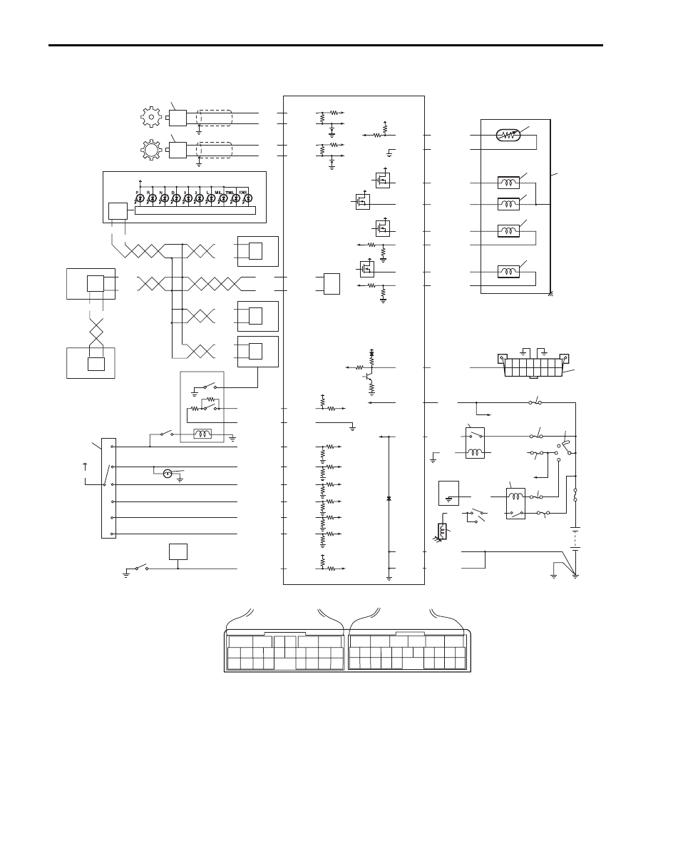
Electronic Shift Control System Wiring Diagram

S6JB0A5102004

13

34

34

34

34

11

12

35

P

R

N

D

2

L

14

5V

12V

12V

12V

12V

BLK

BLK/ORN

BLK/ORN

IG11

BLK/RED

BLK/WHT

+BB

WHT

16

21

17

18

20

12V

19

23

30

25

24

26

27

28

29

WHT

WHT

RED

WHT

RED

RED

6

5

16 15 14 13 12 11

4 3

24 23

21

22

10 9

8

7

2

1

19

20

18 17

E92

17 16

26 25

15 14

6

5

3

4

2

13 12

23 22

24

11 10 9

21 20 19

8 7

18

1

E93

[A]

32

33

RED

BLU

WHT

P

N

GRN

YEL/BLK

ORN

GRN/RED

YEL/RED

BRN/RED

GRN/YEL

PPL/WHT

E92-11

E92-12

E92-16

E92-15

E92-4

E92-2

E92-1

E92-23

E92-6

E92-24

E92-5

E92-3

RED

YEL/GRN

PNK/BLU

PNK/GRN

PNK/WHT

YEL/BLK

YEL/RED

GRN/ORN

GRN/WHT

E92-20

E92-10

E93-4

E93-23

E93-20

E93-1

E93-8

E93-7

E93-19

E93-18

E92-17

E92-7

5

IG11

12V

31

PPL/WHT

34

WHT

RED

34

WHT

RED

34

WHT

RED

WHT

RED

2.5V

WHT

ORN

1

2

E93-5

E93-14

2.5V

BLU

PNK

E93-6

E93-16

15

6

9

BLK/WHT

3

6

4

5

7

8

10

I6JB0A510001-02

Automatic Transmission/Transaxle:  5A-16

[A]: TCM connector (viewed from 

harness side)

9. P/N mode switch

18. Shift solenoid valve-B

27. “IG COIL” fuse

1. Output shaft speed sensor

10. “3” position switch

19. TCC pressure control solenoid 

valve

28. “ST SIG” fuse

2. Input shaft speed sensor

11. Shift lock solenoid

20. Pressure control solenoid valve

29. “ST” fuse

3. Combination meter

12. Brake light switch

21. Valve body assembly

30. AT relay included in integration 

relay No.2 in main fuse box

4. ABS/ESP

® control module

13. Transmission range switch

22. —

31. Starting motor relay

5. ECM

14. Back-up light

23. DLC

32. Inhibit switch

6. 4WD control module (if 

equipped)

15. 4L/N switch (if equipped)

24. Ignition switch

33. Starting motor

7. Keyless start control module

(if equipped)

16. Transmission fluid temperature 

sensor

25. “DOME” fuse

34. CAN driver

8. BCM

17. Shift solenoid valve-A

26. “AT” fuse

35. Meter driver

5A-17 Automatic Transmission/Transaxle: 

Component Location

Electronic Shift Control System Components Location

S6JB0A5103001

7

6

5

4

3

20

1

2

9

8

10

11

12

13

14

15

16

17

18

19

I5JB0A510014-02

Automatic Transmission/Transaxle:  5A-18

Diagnostic Information and Procedures

A/T System Check

S6JB0A5104001

Refer to the following items for the details of each step.

1. Engine

6. Transmission warning light (non-

E-OBD)

11. 4L/N low switch (if equipped)

16. Shift solenoid valve-B

2. Transmission

7. MIL

12. Pressure control solenoid valve

17. Valve body assembly

3. BCM

8. Input shaft speed sensor

13. TCC pressure control solenoid 

valve

18. Transmission range sensor

4. Selector lever assembly 

including “3” position switch

9. Output shaft speed sensor

14. Shift solenoid valve-A

19. ECM

5. P/N mode switch

10. TCM

15. Transmission fluid temperature 

sensor

20. AT relay included power 

integration No.2 in main fuse box

Step

Action

Yes

No

1

)

 Customer complaint analysis

1) Perform customer complaint analysis.

Was customer complaint analysis performed according to 
instruction?

Go to Step 2.

Perform customer 
complaint analysis.

2

)

 DTC / Freeze frame data check, record and clearance

1) Check for DTC (including pending DTC).

Is there any DTC(s)?

Print DTC and freeze 
frame data or write them 
down and clear them by 
referring to “DTC 
Clearance”.
Go to Step 3.

Go to Step 4.

3

)

 Visual inspection

1) Perform visual inspection.

Is there any faulty condition?

Repair or replace 
malfunction part.
Go to Step 11.

Go to Step 5.

4

)

 Visual inspection

1) Perform visual inspection.

Is there any faulty condition?

Repair or replace 
malfunction part.
Go to Step 11.

Go to Step 8.

5

)

 Trouble symptom confirmation

1) Confirm trouble symptom.

Is trouble symptom identified?

Go to Step 6.

Go to Step 7.

6

)

 Rechecking and record of DTC / Freeze frame data

1) Recheck for DTC and freeze frame data referring to 

“DTC Check”.

Is there any DTC(s)?

Go to Step 9.

Go to Step 8.

7

)

 Rechecking and record of DTC / Freeze frame data

1) Recheck for DTC and freeze frame data referring to 

“DTC Check”.

Is there any DTC(s)?

Go to Step 9.

Go to Step 10.

8

)

 A/T Basic Check and A/T Trouble Diagnosis

1) Check and repair according to “A/T Basic Check” and “A/

T Symptom Diagnosis”.

Are check and repair complete?

Go to Step 11.

Check and repair 
malfunction part(s).
Go to Step 11.

9

)

 Troubleshooting for DTC

1) Check and repair according to applicable DTC diag. flow.

Are check and repair complete?

Go to Step 11.

Check and repair 
malfunction part(s).
Go to Step 11.


Content   ..  304  305  306  307   ..