Suzuki Grand Vitara JB627. Manual - part 242


  Index      Suzuki     Suzuki Grand Vitara JB627 - service repair manual


Search            


Content   ..  240  241  242  243   ..


Suzuki Grand Vitara JB627. Manual - part 242


5A-152 Automatic Transmission/Transaxle: 

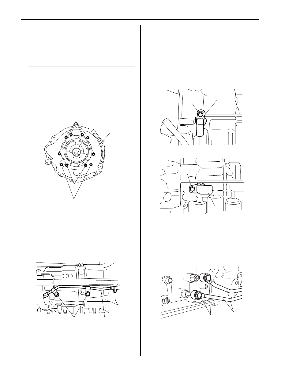
102)Clean threads of automatic transmission housing 

bolts and bolt holes of transmission case, install 
automatic transmission housing (1) to transmission 
case.
Tighten 10 automatic transmission housing bolts to 
specified torque.

NOTE
Make sure to use new converter housing 
bolts (2) and (3).


Tightening torque
Automatic transmission housing bolt (a):  57 
N·m (5.7 kgf-m, 41.5 lb-ft)
Automatic transmission housing bolt (b):  34 
N·m (3.4 kgf-m, 24.5 lb-ft)

103)After applying A/T fluid to new O-ring and then 

install automatic transmission breather pipe (1).

104)Install automatic transmission breather hose.

Tightening 2 automatic transmission breather pipe 
bolts to specified torque.

Tightening torque
Automatic transmission breather pipe bolt (a):  
5.5 N·m (0.55 kgf-m, 4.0 lb-ft)

105)After applying A/T fluid to new O-rings and then 

install them to output shaft speed sensor (1) and 
input shaft speed sensor (2).

106)Install output shaft speed sensor (1) and input shaft 

speed sensor (2).
Tighten transmission speed sensor bolts to specified 
torque.

Tightening torque
Transmission speed sensor bolt (a):  5.5 N·m (
0.55 kgf-m, 4.0 lb-ft)

107)Apply A/T fluid to new 4 union gaskets and then 

install oil cooler pipes (1).
Tighten 2 oil cooler pipe union bolts to specified 
torque.

Tightening torque
Oil cooler pipe union bolt (a):  25 N·m (2.5 kgf-m, 
18.0 lb-ft)

1

(b)

2, (a)

3, (b)

I4JA01512292-01

(a)

1

I4JA01512293-01

2

(a)

(a)

1

I5JA01512005-01

1

(a)

I6JB01510044-01

Automatic Transmission/Transaxle:  5A-153

108)Install transmission range sensor (1) and tighten 

transmission range sensor bolt (4) temporarily.

109)Install grommet, lock washer (2) and nut (3).

Tighten nut to specified torque. After tightening it, 
bend claws of lock washer.

Tightening torque
Manual shift shaft nut (a):  7 N·m (0.7 kgf-m, 5.0 
lb-ft)

110)After turning manual lever shaft fully 

counterclockwise, turn it clockwise by 2 notches and 
set it to “N” range.

111)With neutral reference line (5) and groove (6) in 

transmission range sensor aligned.
Tighten transmission range sensor bolt (4) to 
specified torque.

Tightening torque
Transmission range sensor bolt (b):  13 N·m (1.3 
kgf-m, 9.5 lb-ft)

112)Install manual select lever (1).

Tighten manual select laver nut (2) to specified 
torque.

Tightening torque
Manual select lever nut (a):  12.5 N·m (1.25 kgf-
m, 9.0 lb-ft)

113)Install torque converter (1) to input shaft.

CAUTION

!


Install torque converter, using care not to 
damage oil seal lip of oil pump.


(b)

5

6

2

4

1

3, (a)

I5JA01512006-01

1

2, (a)

I6JB01510045-01

1

I4JA01512298-01

5A-154 Automatic Transmission/Transaxle: 

Automatic Transmission Unit Assembly 
Inspection

S6JB0B5106041

• Hold reverse clutch hub (1), and turn one-way No.2 

clutch assembly (2).
Check that one-way No.2 clutch assembly (2) can be 
turned freely (3) clockwise and locked (4) 
counterclockwise.

• Check that sliding surfaces of discs, plate and flange 

are not worn or burnt. If necessary replace them.

NOTE

• If disc lining is exfoliated, discolored or 

worn hardly, replace all discs.

• If only a part of printed numbers is 

corroded, replace all discs.

• Before assembling new discs, soak them 

in A/T fluid for at least 15 minutes.


• Measure free length of 2nd (No.3) brake piston return 

spring including spring seat.

2nd (No.3) brake piston return spring free length
“a”: 15.72 mm (0.619 in.)

NOTE

• Do not apply excessive force when 

measuring spring free length.

• Perform measurement at several points.


• Measure planetary pinion gear thrust clearance by 

using thickness gauge.
If clearance exceeds limit, replace front planetary gear 
assembly.

Front planetary pinion gear thrust clearance
Standard: 0.20 – 0.60 mm (0.008 – 0.024 in.)
Limit: 0.65 mm (0.026 in.)

1

4

3

2

I4JA01512299-01

I4JA01512300-01


“a”

I4JA01512301-01

I4JA01512302-01

Automatic Transmission/Transaxle:  5A-155

• Measure inside diameter of front planetary gear 

assembly bushing.
If inside diameter exceeds limit, replace front 
planetary gear assembly.

Front planetary gear assembly bushing inside 
diameter limit
57.48 mm (2.263 in.)

• Install one-way No.1 clutch assembly (1) to one-way 

No.1 clutch inner race (2).
Hold one-way No.1 clutch inner race (2), and turn 
one-way No.1 clutch assembly (1).
Check that one-way No.1 clutch assembly (1) can be 
turned freely (3) counterclockwise and locked (4) 
clockwise.
Remove one-way No.1 clutch assembly (1) from one-
way No.1 clutch inner race (2).

• Measure free length of No.1 brake piston return spring 

including spring seat.

No.1 brake piston return spring free length
“a”: 17.05 mm (0.671 in.)

NOTE

• Do not apply excessive force when 

measuring spring free length.

• Perform measurement at several points.


• Measure free length of No.2 brake piston return spring 

including spring seat.

No.2 brake piston return spring free length
“a”: 17.45 mm (0.687 in.)

NOTE

• Do not apply excessive force when 

measuring spring free length.

• Perform measurement at several points.


I4JA01512303-01

3

4

2

1

I4JA01512304-01


“a”

I4JA01512305-01


“a”

I4JA01512306-01


Content   ..  240  241  242  243   ..