Suzuki Grand Vitara JB627. Manual - part 109


  Index      Suzuki     Suzuki Grand Vitara JB627 - service repair manual


Search            


Content   ..  107  108  109  110   ..


Suzuki Grand Vitara JB627. Manual - part 109


1G-19 Fuel System: 

Main Fuel Level Gauge Removal and Installation

S6JB0B1706020

CAUTION

!


• Do not touch resister plate (1) and deform 

arm (2). It may cause main fuel level gauge 
to fail.

• Be very careful not to cause damage to 

fuel tube installed section (sealed section 
in bore). If it be damaged, replace it with 
new one, or fuel will leak from the part.


Removal

1) Remove fuel pump assembly from fuel tank referring 

to “Fuel Pump Assembly Removal and Installation”.

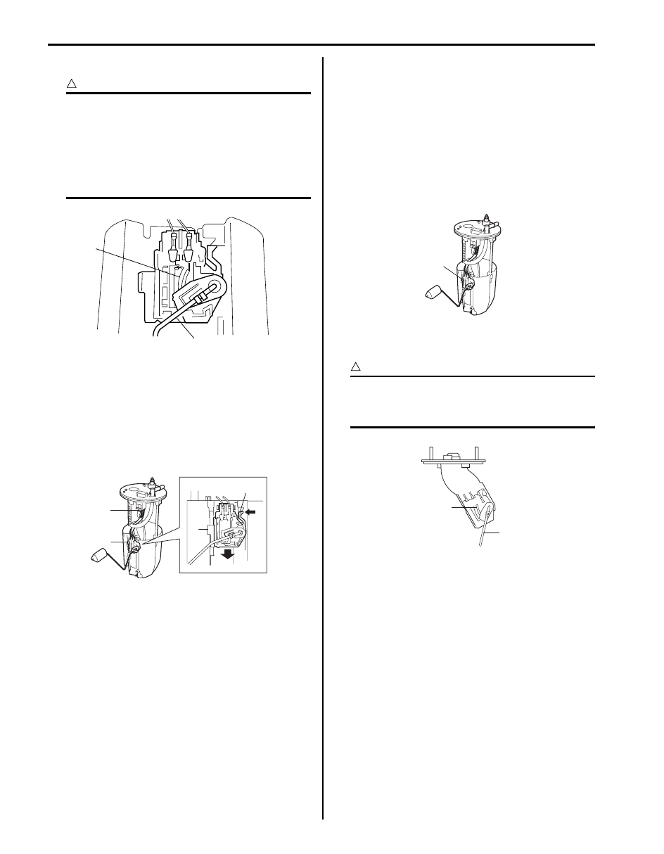
2) Disconnect main fuel level gauge connector (3).
3) With pressing snap-fit part (2), remove main fuel 

level gauge (1) by sliding it in the arrow direction as 
shown in figure.

Installation
Reverse removal procedure for installation.

Fuel Pump Inspection

S6JB0B1706021

• Check fuel pump assembly for damage.
• Check fuel suction filter for evidence of dirt and 

contamination.
If present, replace or clean and check for presence of 
dirt in fuel tank.

• For electrical circuit, refer to “Fuel Pressure Check in 

Section 1A”.

• For inspection of main fuel level gauge (1), refer to 

“Fuel Level Sensor Inspection in Section 9C”.

Sub Fuel Level Gauge Removal and Installation

S6JB0B1706022

CAUTION

!


• Do not touch resister plate (1) and deform 

arm (2). It may cause sub fuel level gauge 
to fail.


1

2

I4RS0A170016-01

1

3

1

2

I5JB0A171026-01

1

I5JB0A171027-01

2

1

I5JB0A171028-01

Fuel System:  1G-20

Removal

1) Remove fuel tank from vehicle. Refer to “Fuel Tank 

Removal and Installation”.

2) Disconnect sub fuel level gauge connector (1).
3) Remove sub fuel level gauge (2).

Installation
Reverse removal procedure for installation noting the 
following.
• Replace O-ring with new one using care not to 

damage it.

• Apply thin coat of fuel to O-ring, and then install sub 

fuel level gauge.

Sub Fuel Level Gauge Inspection

S6JB0B1706023

• Check sub fuel level gauge for damage.
• For inspection of sub fuel gauge (1), refer to “Fuel 

Level Sensor Inspection in Section 9C”.

Specifications

Tightening Torque Specifications

S6JB0B1707001

NOTE
The specified tightening torque is also described in the following.
“Fuel System Components”
“Fuel Hose Disconnecting and Reconnecting”


Reference:
For the tightening torque of fastener not specified in this section, refer to “Fastener Information in Section 0A”.

2

2

1

I5JB0A171029-01

1

I5JB0A171030-01

Fastening part

Tightening torque

Note

N

m

kgf-m

lb-ft

Fuel delivery pipe bolt

25

2.5 

18.0

)

Fuel union bolt

30

3.0 

22.0

)

Fuel pressure regulator bolt

11

1.1 

8.0

)

Fuel filler hose clamp

4

0.4 

3.0

)

 / )

Fuel tank bolt

45

4.5 

32.5

)

Fuel pump assembly nut

11

1.1 

8.0

)

1G-21 Fuel System: 

Special Tools and Equipment

Recommended Service Material

S6JB0B1708001

Special Tool

S6JB0B1708002

Material

SUZUKI recommended product or Specification

Note

Oil

SUZUKI DI O RING OIL(500CC)

P/No.: 99000–25320

)

09912–58421

09912–58432

Checking tool set

Fuel pressure gauge hose

This kit includes the 
following items. 1. Tool body 
and washer, 2. Body plug, 3. 
Body attachment-1, 4. 
Holder, 5. Return hose and 
clamp, 6. Body attachment-2 
and washer, 7. Hose 
attachment-1, 8. Hose 
attachment-2 )

This tool is included in fuel 
pressure gauge set (09912-
58413). )

09912–58442

09912–58490

Fuel pressure gauge

3-way joint & hose

This tool is included in fuel 
pressure gauge set (09912-
58413). ) / )

)

09917–47011

09919–47020

Vacuum pump gauge

Quick joint remover

)

)

09930–88530

SUZUKI scan tool

Injector test lead

)

This kit includes following 
items. 1. Tech 2, 2. PCMCIA 
card, 3. DLC cable, 4. SAE 
16/19 adapter, 5. Cigarette 
cable, 6. DLC loop back 
adapter, 7. Battery power 
cable, 8. RS232 cable, 9. 
RS232 adapter, 10. RS232 
loop back connector, 11. 
Storage case, 12. )

Ignition System:  1H-1

Engine

Ignition System

General Description

Ignition System Construction

S6JB0B1801001

The ignition system is a direct ignition system. It consists of the parts as described below and has an electronic ignition 
control system.
• ECM

It detects the engine and vehicle conditions through the signals from the sensors, determines the most suitable 
ignition timing and time for electricity to flow to the primary coil and sends a signal to the igniter (power unit) in the 
ignition coil assembly.

• Ignition coil assembly (including an igniter and an ignition coil)

The ignition coil assembly has a built-in igniter which turns ON and OFF the current flow to the primary coil 
according to the signal from ECM. When the current flow to the primary coil is turned OFF, a high voltage is induced 
in the secondary coil. One ignition coil is in charge of ignition of one cylinder only.

• Spark plug and noise suppressor
• CMP sensor (Camshaft position sensor) and CKP sensor (Crankshaft position sensor)

Using signals from these sensors, ECM identifies the specific cylinder whose piston is in the compression stroke, 
detects the crank angle and engine speed, adjusts the ignition timing automatically.

• TP sensor, ECT sensor, MAP sensor (if equipped), MAF sensor, IAT sensor, knock sensor, wheel speed sensor 

(VSS) and other sensors / switches

This ignition system does not have a distributor and high-tension cords but each cylinder has an ignition coil assembly 
(igniter and ignition coil) and the secondary voltage which occurred in the ignition coil is sent to the spark plug directly.


Content   ..  107  108  109  110   ..