Suzuki Grand Vitara JB416 / JB420. Manual - part 417


  Index      Suzuki     Suzuki Grand Vitara JB416 / JB420- service repair manual


Search            


Content   ..  415  416  417  418   ..


Suzuki Grand Vitara JB416 / JB420. Manual - part 417


10B-34 Body Electrical Control System: 

Reference waveform No. 5
Vehicle speed pulse output signal (1)

Reference waveform No. 6
CAN communication signal

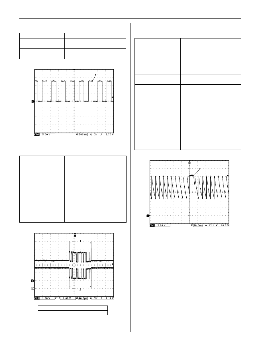
Reference waveform No. 7
Brake fluid level, parking brake or driver seat belt switch 
signal (1)

Measurement terminal CH1: “G30-22” to “G30-12”
Oscilloscope setting

CH1: 5 V / DIV
TIME: 200 ms / DIV

Measurement 
condition

Vehicle speed at 10 km/h (6 
mph)

Measurement terminal CAN communication signal for 

DLC
CH1: “G31-1” to “G30-12”
CH2: “G31-3” to “G30-12”
CAN communication signal for 
each control module
CH1: “G31-2” to “G30-12”
CH2: “G31-4” to “G30-12”

Oscilloscope setting

CH1: 1 V / DIV
CH2: 1 V / DIV
TIME: 40 

µs / DIV

Measurement 
condition

Ignition switch is at ON position

1. CAN communication line signal (High)
2. CAN communication line signal (Low)

I5JB0AA20017-01

I5JB0AA20018-01

Measurement terminal Brake fluid level switch signal:

CH1: “G31-7” to “G30-12”
Parking brake switch signal:
CH1: “G31-8” to “G30-12”
Driver side seat belt switch 
signal:
CH1: “G31-40” to “G30-12”

Oscilloscope setting

CH1: 2 V / DIV
TIME: 20 ms / DIV

Measurement condition Brake fluid level switch:

• Ignition switch is at ON 

position and brake fluid level 
is at specified level

Parking brake switch:
• Ignition switch is at ON 

position and parking brake 
lever is released.

Driver side seat belt switch:
• Ignition switch is at ON 

position and driver seat belt 
is fastened

I5JB0AA20019-01

Body Electrical Control System:  10B-35

Reference waveform No. 8
Oil pressure switch signal (1)

Reference waveform No. 9
Keyless entry receiver signal (1)

Repair Instructions

BCM Removal and Installation

S5JB0AA206001

Removal

1) Disconnect negative cable from battery.
2) Remove steering column hole cover (1).
3) Disconnect connectors from BCM.
4) Remove BCM (2).

Installation
Reverse removal procedure for installation, noting 
following point.
• Connect connectors securely until it clicks.

Outside Air Temperature Sensor Removal and 
Installation

S5JB0AA206002

For removal and installation, refer to “Outside Air 
Temperature Sensor Removal and Installation (If 
Equipped) in Section 9C”.

Measurement terminal CH1: “G31-9” to “G30-12”
Oscilloscope setting

CH1: 2 V / DIV
TIME: 20 ms / DIV

Measurement 
condition

Engine is running and oil 
pressure is in normal condition

I5JB0AA20020-01

Measurement terminal CH2: “G31-19” to “G30-12”
Oscilloscope setting

CH2: 2 V / DIV
TIME: 200 ms / DIV

Measurement condition Lock or unlock button of key 

less entry transmitter is 
pushed

I5JB0AA20021-01

1

2

I5JB0AA20022-01

10B-36 Body Electrical Control System: 

Outside Air Temperature Sensor Inspection

S5JB0AA206003

For inspection, refer to “Outside Air Temperature Sensor 
Inspection (If Equipped) in Section 9C”.

DRL Function Setting Procedure

S5JB0AA206004

DRL is controlled by BCM which has a function to set 
operable / non-operable mode of DRL. With a new BCM, 
its DRL is set to the non-operable mode.
Therefore, when BCM has been replaced in the country 
where DRL operation is required by the statutory 
regulation, set DRL to the operable mode according to 
the procedure described below.
Also, performing the same procedure when DRL is in the 
operable mode will change DRL setting to the non-
operable mode.

1) Turn ignition switch to ON position.

2) Perform Steps a) through f) described blow within 15 

seconds after Step 1).
a) Turn lighting switch to CLEARANCE position.
b) Turn lighting switch to OFF position.
c) Repeat Steps a) and b) five times.
d) Turn lighting switch to HEAD position.
e) Turn lighting switch to OFF position.
f) Repeat Steps a) and e) five times.

3) After Step f), buzzer sounds twice which indicates 

that DRL has been set to operable mode.

NOTE
When DRL setting has been changed from 
operable mode to non-operable mode, buzzer 
sounds once.


4) After confirming buzzer, turn ignition switch to OFF 

position.

Special Tools and Equipment

Special Tool

S5JB0AA208001

SUZUKI scan tool

This kit includes following 
items. 1. Tech 2, 2. PCMCIA 
card, 3. DLC cable, 4. SAE 
16/19 adapter, 5. Cigarette 
cable, 6. DLC loop back 
adapter, 7. Battery power 
cable, 8. RS232 cable, 9. 
RS232 adapter, 10. RS232 
loop back connector, 11. 
Storage case, 12. Power 
supply )

Immobilizer Control System:  10C-1

Control Systems

Immobilizer Control System

Precautions

Precautions in Diagnosing Troubles

S5JB0AA300001

• Before confirming the diagnostic trouble code (DTC), 

do not disconnect connector from ECM, battery cable 
from battery, ground wire harness, or main fuse. Such 
disconnection will erase DTC stored in ECM.

• DTC stored in ECM memory can be checked as well 

as cleared by using SUZUKI scan tool. Before using 
SUZUKI scan tool, read its operator’s manual 
carefully to know how to use it and what functions are 
available.

• Be sure to read “Precautions for Electrical Circuit 

Service in Section 00” before inspection.

• Communication of ECM, BCM, and combination 

meter is established by CAN (Computer Area 
Network). Therefore, handle CAN communication 
lines with care referring to “Precaution for CAN 
Communication System in Section 00”.

Precaution in Replacing ECM

S5JB0AA300002

• If ECM is replaced with new or used one without the 

functionality for the immobilizer control system, the 
engine will not be started. In case of the above, check 
if the newly installed ECM has the functionality for the 
immobilizer control system referring to its part 
number.

• After ECM is replaced with new one or used one, the 

transponder code in the transponder built in the 
ignition key has to be registered with ECM. Or, the 
engine cannot be started up. For the registration 
procedure, refer to “Procedure after ECM 
Replacement”.

Precautions in Handling Immobilizer Control 
System

S5JB0AA300003

• Do not turn ON ignition switch with ignition key in 

contact with another one or quite close to another 
one. Or, the immobilizer control system may detect 
some abnormal condition and prevent the engine from 
starting.

• Do not turn ON ignition switch by using ignition key 

with any type of metal (1) wrapped its grip or in 
contact with it. Or, the immobilizer control system may 
detect some abnormal condition and prevent the 
engine from starting.

• Do not leave ignition key in a place where 

temperature is high. High temperature may cause 
damage to the transponder built in the ignition key.

• Do not turn ignition switch to ON position by bringing 

radio antenna close to coil antenna. Or, the 
immobilizer control system may detect some 
abnormal condition and prevent the engine from 
starting.

I3RH0AA30001-01

1

I3RH0AA30002-01

I3RH0AA30003-01

I3RH0AA30004-01


Content   ..  415  416  417  418   ..