Suzuki Grand Vitara JB416 / JB420. Manual - part 416


  Index      Suzuki     Suzuki Grand Vitara JB416 / JB420- service repair manual


Search            


Content   ..  414  415  416  417   ..


Suzuki Grand Vitara JB416 / JB420. Manual - part 416


10B-30 Body Electrical Control System: 
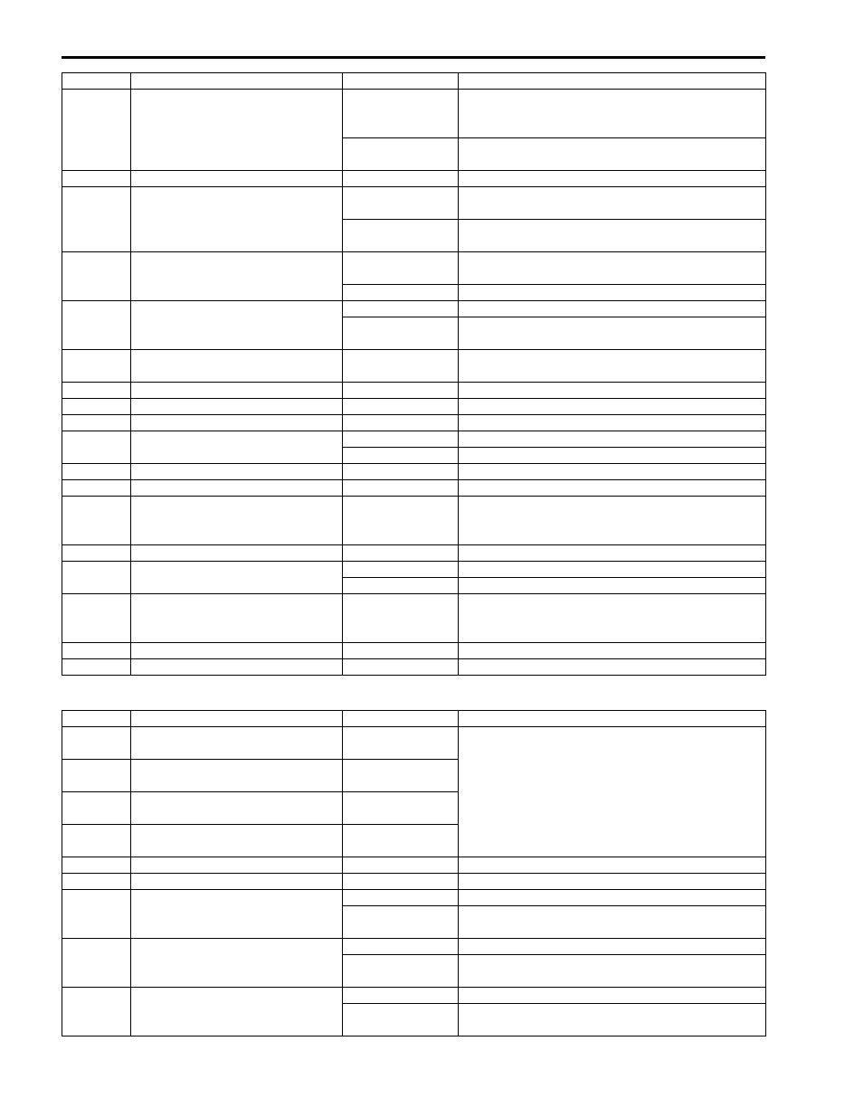
BCM connector “G31”

G30-7

Rear wiper INT switch

0 – 1 V

↑↓

10 – 14 V

Refer to “Reference waveform No. 3: ”

0 V

Ignition switch is at ON position and rear wiper 
switch is at INT position

G30-8

G30-9

Front fog light switch

10 – 14 V

Lighting switch is at CLEARANCE position and 
front fog light switch is at ON position

0 V

Lighting switch is at CLEARANCE position and 
front fog light switch is at OFF position

G30-10 Lighting switch (HEAD)

10 – 14 V

Lighting switch is at any position other than HEAD 
position

0 V

Lighting switch is at HEAD position

G30-11 Lighting switch (CLEARANCE)

10 – 14 V

Lighting switch is at OFF position

0 V

Lighting switch is at any position other than OFF 
position

G30-12

Ground for body electrical 
controller

0 V

Ignition switch is at each position

G30-13

G30-14

G30-15

G30-16 Theft deterrent light

10 – 14 V

Theft deterrent light is not lit up

0 V

Theft deterrent light is lit up

G30-17

G30-18

G30-19 Serial communication line of SDM

*0 – 1 V

↑↓

4 – 6 V

Refer to “Reference waveform No. 4: ”

G30-20

G30-21 Lighting switch (AUTO)

10 – 14 V

Lighting switch is at other than AUTO position

0 V

Lighting switch is at AUTO position

G30-22 Vehicle speed signal output

*0 – 1 V

↑↓

10 – 14 V

Refer to “Reference waveform No. 5: ”

G30-23

G30-24

Terminal

Circuit

Normal voltage

Condition

Terminal

Circuit

Normal voltage

Condition

G31-1

CAN communication line (high) for 
DLC

*2.5 – 3.6 V

Refer to “Reference waveform No. 6: ”

G31-2

CAN communication line (high) for 
each control module

*2.5 – 3.6 V

G31-3

CAN communication line (low) for 
DLC

*1.6 – 2.5 V

G31-4

CAN communication line (low) for 
each control module

*1.6 – 2.5 V

G31-5

G31-6

G31-7

Brake fluid level switch

*5 – 12 V

Refer to “Reference waveform No. 7: ”

0 V

Ignition switch is at ON position and brake fluid 
level is lower than MIN level

G31-8

Parking brake switch

*5 – 12 V

Refer to “Reference waveform No. 7: ”

0 V

Ignition switch is at ON position and parking brake 
lever is pulled up

G31-9

Oil pressure switch

*6 – 14 V

Refer to “Reference waveform No. 8: ”

0 V

Ignition switch is at ON position and engine is at 
stop

Body Electrical Control System:  10B-31

G31-10 Generator “L” terminal

10 – 14 V

Engine is running

0 V

Ignition switch is at ON position

G31-11

G31-12 Tail light relay control

10 – 14 V

Lighting switch is at OFF position

0 V

Lighting switch is at any position other than OFF 
position

G31-13 Rear wiper control

10 – 14 V

Ignition switch is at ON position and rear wiper is 
not in operation

0 V

Ignition switch is at ON position and rear wiper is in 
operation

G31-14

Rear end door window defogger 
control

10 – 14 V

Engine is running and rear end door window 
defogger is not in operation

0 V

Engine is running and rear end door window 
defogger is in operation

G31-15 Horn control

10 – 14 V

Horn is not in operation

0 V

Horn is in operation

G31-16 DRL control

10 – 14 V

Engine is running and lighting switch is at 
CLEARANCE or OFF position

0 V

Engine is running and lighting switch is at HEAD 
position

G31-17 Front fog light control

10 – 14 V

Lighting switch is at CLEARANCE position and 
front fog light switch is at OFF position

0 V

Lighting switch is at CLEARANCE position and 
front fog light switch is at ON position

G31-18 Power supply for keyless receiver

4 – 6 V

Ignition switch is at ON position

G31-19 Signal for keyless receiver

*0 – 1 V

↑↓

10 – 14 V

Refer to “Reference waveform No. 9: ”

G31-20 Ground for keyless receiver

0 V

Ignition switch is at each position

G31-21

Sensor ground for outside air 
temperature sensor

0 V

Ignition switch is at each position

G31-22

Sensor ground for auto light 
sensor

0 V

Ignition switch is at each position

G31-23 Auto-on headlight sensor

0.2 V

Ignition switch is at ON position and cover auto-on 
headlight sensor lens by hand

3 – 4 V

Ignition switch is at ON position and light auto-on 
headlight sensor lens by 100 W lights

G31-24 Outside air temperature sensor

About 1.5 V

Ignition switch is at ON position and outside air 
temperature approx. 20 

°C (68 °F)

G31-25 Power supply for auto light sensor

4 – 6 V

Ignition switch is at ON position

G31-26 Manual door lock switch (Unlock)

4 – 6 V

Manual door lock switch is at any position other 
than unlock position

0 V

Manual door lock switch is at unlock position

G31-27 Manual door lock switch (Lock)

4 – 6 V

Manual door lock switch is at any position other 
than lock position

0 V

Manual door lock switch is at lock position.

G31-28 Power/Normal mode switch

4 – 6 V

Ignition switch is at ON position and Power/Normal 
mode switch is at ON position

0 V

Ignition switch is at ON position and Power/Normal 
mode switch is at OFF position

G31-29

G31-30

G31-31

G31-32

G31-33

G31-34

Turn signal / hazard warning relay 
control

0 V

Hazard warning switch is at ON position

10 – 14 V

Hazard warning switch is at OFF position

G31-35

Serial communication line of data 
link connector

10 – 14 V

Ignition switch is at ON position

Terminal

Circuit

Normal voltage

Condition

10B-32 Body Electrical Control System: 

BCM connector “G32”

G31-36

Driver side door key cylinder 
switch (Unlock)

10 – 14 V

Driver side key cylinder switch is at any position 
other than unlock position

0 V

Driver side key cylinder switch is at unlock position

G31-37

Driver side door key cylinder 
switch (lock)

10 – 14 V

Driver side key cylinder switch is at any position 
other than lock position

0 V

Driver side key cylinder switch is at lock position

G31-38

Door switch (rear end door and 
other than driver side door)

10 – 14 V

Rear right and left side door, passenger side door, 
rear end door and rear end door are closed

0 V

Any one of the door is opened (except driver side 
door)

G31-39 Driver side door switch

10 – 14 V

Driver side door is closed

0 V

Driver side door is opened

G31-40 Driver seat belt switch

*5 – 12 V

Refer to “Reference waveform No. 7: ”

0 V

Ignition switch is at ON position and driver seat 
belt is unfastened

Terminal

Circuit

Normal voltage

Condition

Terminal

Circuit

Normal voltage

Condition

G32-1

Ground for door lock motor

0 V

Ignition switch is at each position

G32-2

Rear door lock actuator motor 
control (Unlock)

10 – 14 V

Unlock signal is output for rear door lock actuators

0 V

Unlock signal is not output for rear door lock 
actuators

G32-3

Door lock actuator motor control 
(Lock)

10 – 14 V

Lock signal is output for all door lock actuators

0 V

Lock signal is not output for all door lock actuators

G32-4

G32-5

Power supply for door lock 
actuator motor

10 – 14 V

Ignition switch is at each position

G32-6

G32-7

Rear end door lock actuator motor 
control (Unlock)

10 – 14 V

Unlock signal is output for rear end door lock 
actuator

0 V

Unlock signal is not output for rear end door lock 
actuator

G32-8

Driver side door lock actuator 
motor control (Unlock)

10 – 14 V

Unlock signal is output for driver side door lock 
actuator

0 V

Unlock signal is not output for driver side door lock 
actuator

G32-9

Passenger side door lock actuator 
motor control (Unlock)

10 – 14 V

Unlock signal is output for passenger side door 
lock actuator

0 V

Unlock signal is not output for passenger side door 
lock actuator

G32-10

Door lock actuator motor control 
(Dead lock cancel)

10 – 14 V

Driver side key cylinder is turned to unlock position

0 V

Driver side key cylinder is at any position other 
than unlock position

G32-11

Door lock actuator motor control 
(Dead lock set)

10 – 14 V

Driver side key cylinder is turned to lock twice 
within 3 seconds

0 V

Driver side key cylinder is at any position other 
than lock position

G32-12

Headlight high beam monitor 
signal

10 – 14 V

Lighting switch is at HEAD position and dimmer 
switch is at low beam position

0 V

Lighting switch is at HEAD position and dimmer 
switch is at high beam position

G32-13 Power supply for interior light

10 – 14 V

Ignition switch is at each position

G32-14

G32-15 Interior light control

10 – 14 V

Interior light switch is at DOOR position and 
interior light is not lit up

0 V

Interior light switch is at DOOR position and 
interior light is lit up

Body Electrical Control System:  10B-33

Reference waveform No. 1
HVAC control module serial communication signal (1)

Reference waveform No. 2
HVAC control module and information display serial 
communication signal (1)

Reference waveform No. 3
Rear wiper LOW or INT signal (1)

Reference waveform No. 4
SDM communication signal (1)

Measurement terminal CH1: “G30-4” to “G30-12”
Oscilloscope setting

CH1: 5 V / DIV
TIME: 2 ms / DIV

Measurement 
condition

Ignition switch is at ON position

Measurement terminal CH2: “G30-5” to “G30-12”
Oscilloscope setting

CH1: 5 V/DIV
TIME: 10 ms/DIV

Measurement 
condition

Ignition switch is at ON position

I5JB0AA20013-01

I5JB0AA20014-01

Measurement terminal Rear wiper LOW signal:

CH1: “G30-6” to “G30-12”
Rear wiper INT signal:
CH1: “G30-7” to “G30-12”

Oscilloscope setting

CH2: 5 V/DIV
TIME: 10 ms/DIV

Measurement 
condition

Rear wiper LOW signal:
• Ignition switch is at ON 

position, rear wiper switch is 
at any position other than 
LOW position

Rear wiper INT signal:
• Ignition switch is at ON 

position, rear wiper switch is 
at any position other than 
INT position

Measurement terminal CH1: “G30-19” to “G30-12”
Oscilloscope setting

CH1: 2 V/DIV
TIME: 400 ms/ DIV

Measurement 
condition

Ignition switch is at ON position

I5JB0AA20015-01

I5JB0AA20016-01


Content   ..  414  415  416  417   ..