Suzuki Grand Vitara JB416 / JB420. Manual - part 408


  Index      Suzuki     Suzuki Grand Vitara JB416 / JB420- service repair manual


Search            


Content   ..  406  407  408  409   ..


Suzuki Grand Vitara JB416 / JB420. Manual - part 408


10A-7 Cruise Control System: 
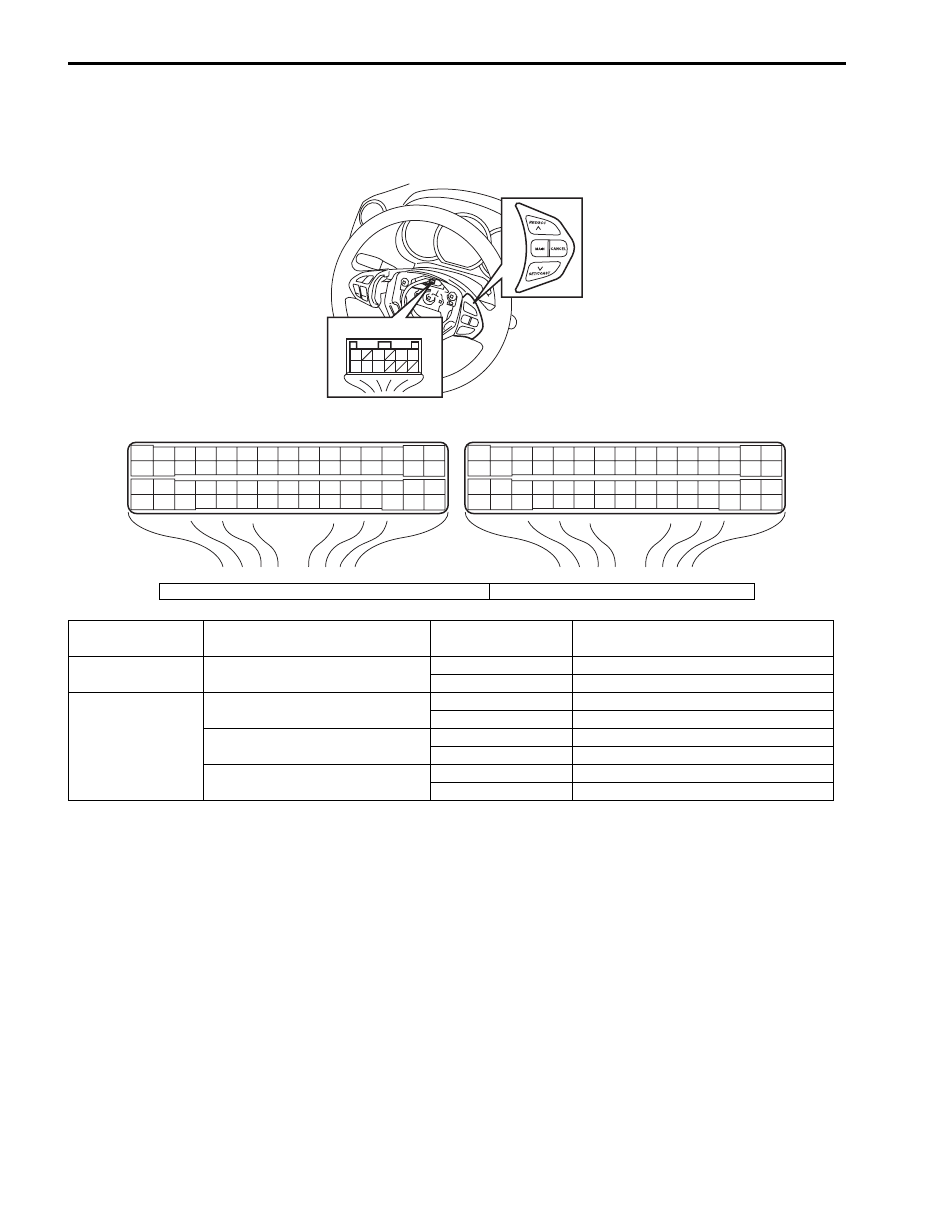
Resistance Check

1) Remove driver air bag (inflator) module from steering wheel referring to “Driver Air Bag (Inflator) Module Removal 

and Installation in Section 8B”.

2) Measure resistance between the following terminals with ECM connector disconnected.

E23

C37

3

4

18

19

5

6

7

10

11

17

20

47

46

49

50

51

21

22

52

16

25

9

24

14
29

55

57

54 53

59

60

58

2

26

27

28

15
30

56

48

32

31

34

35

36

37

40

42

39 38

44

45

43

41

33

1

12

13

23

8

3

4

18

19

5

6

7

10

11

17

20

47

46

49

50

51

21

22

52

16

25

9

24

14
29

55

57

54 53

59

60

58

2

26

27

28

15
30

56

48

32

31

34

35

36

37

40

42

39 38

44

45

43

41

33

1

12

13

23

8

1

5

3

6

7 8 9

G54

[A]

[B]

I5JB0AA10005-03

[A]: Cruise control switch connector (viewed from harness side)

[B]: ECM connector (viewed from harness side)

Terminals

Circuit

Standard 

Resistance

Condition

G54-1 – E23-6

MAIN switch circuit

No continuity

MAIN switch is not pressed.

About 1 

MAIN switch is pressed.

E23-21 – E23-22

CANCEL switch circuit

No continuity

CANCEL switch is not pressed.

About 1.5 

CANCEL switch is pressed.

RES/ACC switch circuit

No continuity

RES/ACC switch is not pressed.

About 911 

RES/ACC switch is pressed.

SET/COAST switch circuit

No continuity

SET/COAST switch is not pressed.

About 222 

SET/COAST switch is pressed.

Cruise Control System:  10A-8

Repair Instructions

Cruise Control Switch Removal and Installation

S5JB0AA106001

For removal and installation, refer to “Remote Audio 
Control Switch Removal and Installation in Section 9C”.

Cruise Control Switch Inspection

S5JB0AA106002

NOTE
Never disassemble cruise control switch. 
Disassembly will spoil its original functions.


1) Remove driver air bag (inflator) module referring to 

“Driver Air Bag (Inflator) Module Removal and 
Installation in Section 8B”.

2) Disconnect cruise control switch connector (1) from 

control coil.

3) Check cruise control switch as follow.

For MAIN Switch
Check for continuity between “1” and “8” terminals under 
each condition below.
If check result is not satisfactory, replace cruise control 
switch (2).

Cruise main switch (3) specification: [B]
Switch button released: Infinity
Switch button pressed: Continuity

For Set/Coast, Res/Acc and Cancel Switch
Check for resistance between “7” and “9” terminals 
under each condition below.
If check result is not satisfactory, replace cruise control 
switch (2).

SET/COAST, RES/ACC and CANCEL switches 
resistance: [C]
All switches released (OFF): Infinity
CANCEL switch (4) pressed (ON): About 0 

SET/COAST switch (5) pressed (ON): 217 – 223 

RES/ACC switch (6) pressed (ON): 900 – 920 

CPP Switch (for Cruise Control) Removal and 
Installation

S5JB0AA106003

Removal

1) Disconnect connector of CPP switch (for cruise 

control) (1) with ignition switch OFF.

2) Remove CPP switch (for cruise control) (1) from 

pedal bracket.

[A]: Cruise control switch connector viewed from harness side

2. Brake light switch

1

5

3

6

7 8 9

1

5

3

6

7 8 9

[B]

[C]

[A]

6

1

4

5

2

3

I5JB0AA10006-01

1

2

I5JB0AA10007-01

10A-9 Cruise Control System: 

Installation

1) Install CPP switch (for cruise control) (2) to pedal 

bracket.

2) With clutch pedal (1) released, adjust switch position 

so that clearance between end of thread and clutch 
pedal bracket is within specification.

Clearance between end of thread and clutch 
pedal bracket
“a”: 0.5 – 1.5 mm (0.02 – 0.059 in.)

3) Tighten lock nut (3) to specified torque.

Tightening torque
CPP switch lock nut (a):  7.5 N·m (0.75 kgf-m, 5.5 
lb-ft)

4) Connect connector to CPP switch (for cruise control) 

(2) securely.

Clutch Pedal Position (CPP) Switch (for Cruise 
Control) Inspection and Adjustment

S5JB0AA106004

Inspection
Check for resistance between terminals under each 
condition below. If check result is not satisfactory, 
replace.

CPP switch (for cruise control) resistance
When switch shaft is pushed [A]: No continuity
When switch shaft is free [B]: Continuity

Adjustment
For adjustment, refer to “Installation” under “CPP Switch 
(for Cruise Control) Removal and Installation”. 

Stop (Brake) Lamp Switch Removal and 
Installation

S5JB0AA106007

For removal and installation, refer to “Brake Light Switch 
Adjustment in Section 4A”.

Stop (Brake) Lamp Switch Inspection

S5JB0AA106005

Check for continuity between terminals referring to “Stop 
(Brake) Lamp Switch Inspection in Section 9B”.

ECM Removal and Installation

S5JB0AA106006

For removal and installation, refer to “Engine Control 
Module (ECM) Removal and Installation in Section 1C”.

Specifications

Tightening Torque Specifications

S5JB0AA107001

Reference:
For the tightening torque of fastener not specified in this section, refer to “Fastener Information in Section 0A”.

“a”

2

1

3

I5JB0AA10008-01

I5JB0AA10009-01

Fastening part

Tightening torque

Note

N

m

kgf-m

lb-ft

CPP switch lock nut

7.5

0.75 

5.5

)

Body Electrical Control System:  10B-1

Control Systems

Body Electrical Control System

Precautions

Precautions in Diagnosing Trouble

S5JB0AA200001

• Diagnostic information stored in BCM memory can be cleared as well as checked by using SUZUKI scan tool. 

Before using scan tool, read its Operator’s (Instruction) Manual carefully to have good understanding as to what 
functions are available and how to use it.

• Be sure to read “Precautions for Electrical Circuit Service in Section 00” before inspection and observe what is 

written there.

• Communication of ECM, TCM (if equipped), BCM, ABS hydraulic unit/control module (if equipped), 4WD control 

module (if equipped), keyless start control module (if equipped) and combination meter is established by CAN 
(Controller Area Network).
Therefore, be sure to read “Precaution for CAN Communication System in Section 00” before inspection and handle 
CAN communication line.

General Description

BCM General Description

S5JB0AA201001

The BCM incorporates relays and controllers which are used for the following systems and controls them.
• Power door lock (if equipped)
• Keyless entry (if equipped)
• Door lock function of keyless start system (if equipped)
• Rear wiper
• Combination meter
• Interior light / luggage room light
• Warning buzzer
• Rear end door window defogger and door miller heater (if equipped)
• DRL (if equipped)
• Auto-on headlight (if equipped)
• Front fog light (if equipped)
• Theft deterrent light
Also, the BCM has a function to cause the interior light and open door warning lamp in the combination meter to turn 
off when any door is left open for longer than 15 minutes to reduce wasteful battery consumption.
In addition, it is possible to check operation of actuator which is controlled by BCM by using the output test function of 
SUZUKI scan tool to operate actuator simulatively.

CAN Communication System Description for BCM

S5JB0AA201002

BCM communicates with each of ECM, TCM (if equipped), keyless start control module (if equipped), 4WD control 
module (if equipped) and combination meter about the following data. For details of CAN communication, refer to 
“CAN Communication System Description in Section 1A”.
• Data which BCM receives from ECM

– Engine speed signal
– Engine coolant temperature signal
– Vehicle speed signal
– Immobilizer registration request signal
– Stop (brake) lamp switch signal
– Magnet clutch signal
– A/C refrigerant pressure signal
– Distance kilometers per liter of fuel signal


Content   ..  406  407  408  409   ..