Suzuki Grand Vitara JB416 / JB420. Manual - part 4


  Index      Suzuki     Suzuki Grand Vitara JB416 / JB420- service repair manual


Search            


Content   ..  1  2  3  4  5  ..


Suzuki Grand Vitara JB416 / JB420. Manual - part 4


00-13 Precautions: 

Repair Instructions

Electrical Circuit Inspection Procedure

S5JB0A0006001

While there are various electrical circuit inspection 
methods, described here is a general method to check 
its open and short circuit by using an ohmmeter and a 
voltmeter.

Open Circuit Check
Possible causes for the open circuit are as follows. As 
the cause is in the connector or terminal in many cases, 
they need to be checked particularly carefully.
• Loose connection of connector
• Poor contact of terminal (due to dirt, corrosion or rust 

on it, poor contact tension, entry of foreign object etc.)

• Wire harness being open
When checking system circuits including an electronic 
control unit such as ECM, TCM, ABS control module, 
etc., it is important to perform careful check, starting with 
items which are easier to check.

1) Disconnect negative cable from battery
2) Check each connector at both ends of the circuit 

being checked for loose connection. Also check lock 
condition of connector if equipped with connector 
lock.

3) Using a test male terminal, check both terminals of 

the circuit being checked for contact tension of its 
female terminal. Check each terminal visually for 
poor contact (possibly caused by dirt, corrosion, rust 
entry of foreign object, etc.). At the same time, check 
to make sure that each terminal is locked in the 
connector fully.

4) Using continuity check or voltage check the following 

procedure, check the wire harness for open circuit 
and poor connection with its terminals. Locate 
abnormality, if any.
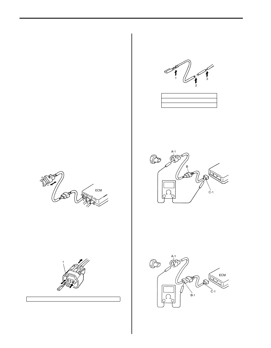
Continuity Check

1) Measure resistance between connector terminals at 

both ends of the circuit being checked (between “A-
1” and “C-1” in the figure). If no continuity is indicated 
(infinity or over limit), that means that the circuit is 
open between terminals “A-1” and “C-1”.

2) Disconnect the connector included in the circuit 

(connector-B in the figure) and measure resistance 
between terminals “A-1” and “B-1”.
If no continuity is indicated, that means that the 
circuit is open between terminals “A-1” and “B-1”. If 
continuity is indicated, there is an open circuit 
between terminals “B-1” and “C-1” or an abnormality 
in connector-B.

1. Check contact tension by inserting and removing just for once.

I2RH01010049-01

I2RH01010050-01

1. Looseness of crimping
2. Open
3. Thin wire (single strand of wire)

I2RH01010051-01

I2RH01010052-01

I2RH01010053-01

Precautions: 00-14

Voltage Check
If voltage is supplied to the circuit being checked, voltage 
check can be used as circuit check.

1) With all connectors connected and voltage applied to 

the circuit being checked, measure voltage between 
each terminal and body ground.
a) If measurements were taken as shown in the 

figure and results were as listed in the following, 
it means that the circuit is open between 
terminals “B-1” and “A-1”.

Voltage between each terminal and body 
ground
“C-1” and body ground: Approx. 5 V
“B-1” and body ground: Approx. 5 V
“A-1” and body ground: 0 V

b) Also, if measured values were as listed in the 

following, it means that there is a resistance 
(abnormality) of such level that corresponds to 
the voltage drop in the circuit between terminals 
“A-1” and “B-1”.

Voltage between
“C-1” and body ground: Approx. 5 V
“B-1” and body ground: Approx. 5 V
“A-1” and body ground: Approx. 3 V
“A-1” and “B-1”: 2V voltage drop

Short Circuit Check (Wire Harness to Ground)

1) Disconnect negative cable at battery.
2) Disconnect connectors at both ends of the circuit to 

be checked.

NOTE
If the circuit to be checked is connected to 
other parts (1), disconnect all connectors of 
those parts.
Otherwise, diagnosis will be misled.


3) Measure resistance between terminal at one end of 

circuit (“A-1” terminal in the figure) and body ground. 
If continuity is indicated, it means that there is a short 
to ground between terminals “A-1” and “C-1” of the 
circuit.

4) Disconnect the connector included in circuit 

(connector B) and measure resistance between “A-
1” and body ground. 
If continuity is indicated, it means that the circuit is 
shorted to the ground between terminals “A-1” and 
“B-1”.

I5RH01000005-01

1. To other parts

1. To other parts

I5RH01000006-01

I2RH01010056-01

00-15 Precautions: 

Intermittent and Poor Connection Inspection

S5JB0A0006002

Most intermittent are caused by faulty electrical 
connections or wiring, although a sticking relay or 
solenoid can occasionally be at fault. When checking it 
for proper connection, perform careful check of suspect 
circuits for:
• Poor mating of connector halves, or terminals not fully 

seated in the connector body (backed out).

• Dirt or corrosion on the terminals. The terminals must 

be clean and free of any foreign material which could 
impede proper terminal contact. However, cleaning 
the terminal with a sand paper or the like is prohibited. 

• Damaged connector body, exposing the terminals to 

moisture and dirt, as well as not maintaining proper 
terminal orientation with the component or mating 
connector.

• Improperly formed or damaged terminals.

Check each connector terminal in problem circuits 
carefully to ensure good contact tension by using the 
corresponding mating terminal.
If contact tension is not enough, reform it to increase 
contact tension or replace.

• Poor terminal-to-wire connection.

Check each wire harness in problem circuits for poor 
connection by shaking it by hand lightly. If any 
abnormal condition is found, repair or replace.

• Wire insulation which is rubbed through, causing an 

intermittent short as the bare area touches other 
wiring or parts of the vehicle.

• Wiring broken inside the insulation. This condition 

could cause continuity check to show a good circuit, 
but if only 1 or 2 strands of a multi-strand-type wire 
are intact, resistance could be far too high.
If any abnormality is found, repair or replace.

1. Check contact tension by inserting and removing just once.
2. Check each terminal for bend and proper alignment.

I2RH01010057-01

I5RH01000007-01

I2RH01010059-01

I2RH01010060-01

Table of Contents 0- i

0

Section 0

CONTENTS

General Information

General Information ................................ 0A-1

General Description .............................................0A-1

Abbreviations ...................................................... 0A-1
Symbols .............................................................. 0A-2
Wire Color Symbols ............................................ 0A-3
Fastener Information........................................... 0A-3
Vehicle Lifting Points........................................... 0A-5
Engine Supporting Points ................................... 0A-7
Vehicle Identification Number ............................. 0A-7
Engine Identification Number.............................. 0A-7
Transmission Identification Number.................... 0A-7

Component Location ...........................................0A-8

Warning, Caution and Information Label 

Location ............................................................ 0A-8

Maintenance and Lubrication................. 0B-1

Precautions...........................................................0B-1

Precautions for Maintenance and Lubrication..... 0B-1

Scheduled Maintenance ......................................0B-1

Maintenance Schedule under Normal Driving 

Conditions ......................................................... 0B-1

Maintenance Recommended under Severe 

Driving Conditions............................................. 0B-2

Repair Instructions ..............................................0B-4

Engine Accessory Drive Belt Inspection ............. 0B-4
Engine Accessory Drive Belt Replacement......... 0B-4
Valve Lash (Clearance) Inspection ..................... 0B-4
Engine Oil and Filter Change.............................. 0B-5
Engine Coolant Change...................................... 0B-6
Exhaust system Inspection ................................. 0B-7
Spark Plugs Replacement .................................. 0B-7
Air Cleaner Filter Inspection................................ 0B-7
Air Cleaner Filter Replacement ........................... 0B-7
Fuel Lines and Connections Inspection .............. 0B-7
Fuel Filter Replacement...................................... 0B-7
Fuel Tank Inspection........................................... 0B-7

Crankcase Ventilation Hoses and 

Connections Inspection (Vehicle without A/F 
Sensor)..............................................................0B-7

PCV Valve Inspection .........................................0B-7
Fuel Evaporative Emission Control System 

Inspection..........................................................0B-8

Brake Discs and Pads Inspection .......................0B-8
Brake Drums and Shoes Inspection....................0B-8
Brake Hoses and Pipes Inspection .....................0B-8
Brake Fluid Change ............................................0B-9
Parking Brake Lever and Cable Inspection.........0B-9
Clutch Fluid Inspection........................................0B-9
Tire / Wheel Inspection and Rotation ..................0B-9
Wheel Discs Inspection.....................................0B-10
Wheel Bearing Inspection .................................0B-10
Suspension System Inspection .........................0B-10
Steering System Inspection ..............................0B-10
Propeller Shafts and Drive Shafts Inspection....0B-11
Manual Transmission Oil Inspection .................0B-11
Manual Transmission Oil Change .....................0B-12
Automatic Transmission Fluid Inspection..........0B-12
Automatic Transmission Fluid Change .............0B-12
Automatic Transmission Fluid Cooler Hose 

Inspection........................................................0B-12

Transfer Oil Inspection (If Equipped) ................0B-12
Differential Oil Inspection ..................................0B-12
Transfer (If Equipped) and Differential Oil 

Change............................................................0B-12

Power Steering (P/S) System Inspection ..........0B-13
All Hinges, Latches and Locks Inspection.........0B-13
HVAC Air Filter Inspection (If Equipped)...........0B-13
HVAC Air Filter Replacement (If Equipped) ......0B-13
Final Inspection for Maintenance Service .........0B-13

Specifications.....................................................0B-15

Tightening Torque Specifications......................0B-15

Special Tools and Equipment ...........................0B-15

Recommended Fluids and Lubricants...............0B-15
Special Tool ......................................................0B-15


Content   ..  1  2  3  4  5  ..