Suzuki Grand Vitara JB416 / JB420. Manual - part 3


  Index      Suzuki     Suzuki Grand Vitara JB416 / JB420- service repair manual


Search            


Content   ..  1  2  3  4  ..


Suzuki Grand Vitara JB416 / JB420. Manual - part 3


00-9 Precautions: 

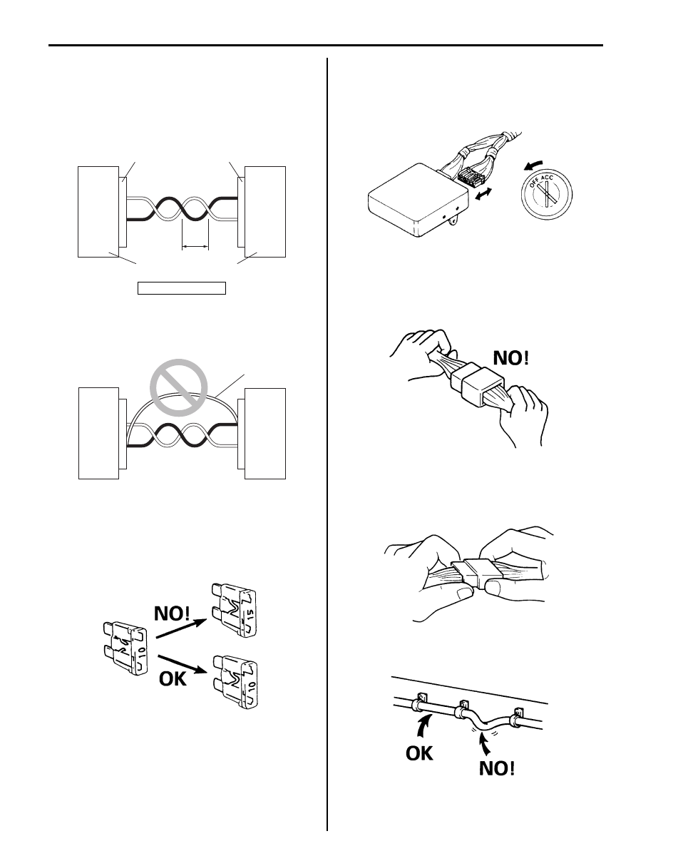
Precaution for CAN Communication System

S5JB0A0000005

• The loose (1) in the wire harnesses twist of the CAN 

lines except around the connector (3) should be within 
100 mm (3.9 in.). Refer to the wiring diagram for the 
CAN lines discrimination. Excessively-loosed lines 
may be influenced by the electric noise.

• Do not connect terminals of the CAN line using a 

bypass wire (1). Otherwise, the CAN line may be 
influenced by the electric noise.

Precautions for Electrical Circuit Service

S5JB0A0000006

• When replacing a fuse, make sure to use a fuse of the 

specified capacity. Use of a fuse with a larger capacity 
will cause a damage to the electrical parts and a fire.

• When disconnecting and connecting coupler, make 

sure to turn ignition switch OFF, or electronic parts 
may get damaged.

• When disconnecting connectors, never pull the wiring 

harness. Unlock the connector lock first and then pull 
them apart by holding connectors themselves.

• When connecting connectors, also hold connectors 

and put them together until they lock securely (a click 
is heard).

• When installing the wiring harness, fix it with clamps 

so that no slack is left.

2. Controller

3

3

2

2

1

I4JA01000002-01

1

I4JA01000003-01

I2RH01010038-01

I2RH01010039-01

I2RH01010040-01

I2RH01010041-01

I2RH01010042-01

Precautions: 00-10

• When installing vehicle parts, be careful so that the 

wiring harness is not interfered with or caught by any 
other part.

• To avoid damage to the harness, protect its part which 

may contact against a part forming a sharp angle by 
winding tape or the like around it.

• Be careful not to touch the electrical terminals of parts 

which use microcomputers (e.g. electronic control unit 
like as ECM, PCM, P/S controller, etc.). The static 
electricity from your body can damage these parts.

• Never connect any tester (voltmeter, ohmmeter, or 

whatever) to electronic control unit when its coupler is 
disconnected. Attempt to do it may cause damage to 
it.

• Never connect an ohmmeter to electronic control unit 

with its coupler connected to it. Attempt to do it may 
cause damage to electronic control unit and sensors.

• Be sure to use a specified voltmeter / ohmmeter. 

Otherwise, accurate measurements may not be 
obtained or personal injury may result. If not specified, 
use a voltmeter with high impedance (M 

Ω/V 

minimum) or a digital type voltmeter.

• When taking measurements at electrical connectors 

using a tester probe, be sure to insert the probe (2) 
from the wire harness side (backside) of the 
connector (1).

• When connecting meter probe (2) from terminal side 

of coupler (1) because it can’t be connected from 
harness side, use extra care not to bend male 
terminal of coupler of force its female terminal open 
for connection.
In case of such coupler as shown connect probe as 
shown to avoid opening female terminal.
Never connect probe where male terminal is 
supposed to fit.

• When checking connection of terminals, check its 

male half for bend and female half for excessive 
opening and both for locking (looseness), corrosion, 
dust, etc.

• Before measuring voltage at each terminal, check to 

make sure that battery voltage is 11 V or higher. Such 
terminal voltage check at low battery voltage will lead 
to erroneous diagnosis.

I2RH01010043-01

I2RH01010044-01

I3RM0A000004-01

I2RH01010046-01

I2RH01010047-01

I2RH01010048-01

00-11 Precautions: 

Precautions for Installing Mobile 
Communication Equipment

S5JB0A0000004

When installing mobile communication equipment such 
as CB (Citizens-Band)-radio or cellular-telephone, be 
sure to observe the following precautions.
Failure to follow cautions may adversely affect electronic 
control system.
• Keep the antenna as far away as possible from the 

vehicle’s electronic control unit.

• Keep the antenna feeder more than 20 cm (7.9 in.) 

away from electronic control unit and its wire 
harnesses.

• Do not run the antenna feeder parallel with other wire 

harnesses.

• Confirm that the antenna and feeder are correctly 

adjusted.

Air Bag Warning

S5JB0A0000007

WARNING

!


For vehicles equipped with Supplemental 
Restraint (Air Bag) System:
• Service on and around the air bag system 

components or wiring must be performed 
only by an authorized SUZUKI dealer. Refer 
to “Air Bag System Components, Wiring 
and Connectors Location in Section 8B” in 
order to confirm whether you are 
performing service on or near the air bag 
system components or wiring. Please 
observe all “WARNING”s and “Precautions 
on Service and Diagnosis of Air Bag 
System in Section 8B” before 
performing 
service on or around the air bag system 
components or wiring. Failure to follow 
“WARNING”s could result in unintentional 
activation of the system or could render 
the system inoperative. Either of these two 
conditions may result in severe injury.

• Technical service work must be started at 

least 90 seconds after the ignition switch is 
turned to the “LOCK” position and the 
negative cable is disconnected from the 
battery. Otherwise, the system may be 
activated by reserve energy in the Sensing 
and Diagnostic Module (SDM).


Discharge Headlight Warning

S5JB0A0000014

WARNING

!


When performing service on and around the 
discharge headlight, observe “Precautions 
for Discharge Headlight Service (If Equipped) 
in Section 9B”. Ne
glecting the warnings may 
result in personal injury.


A/C System Caution

S5JB0A0000015

CAUTION

!


The air conditioning system of this vehicle 
uses refrigerant HFC-134a (R-134a).
None of refrigerant, compressor oil and 
component parts is interchangeable between 
two types of A/C: one using refrigerant CFC-
12 (R-12) and the other using refrigerant HFC-
134a (R-134a).
Be sure to check which refrigerant is used 
before any service work including inspection 
and maintenance. For identification between 
these two types, refer to “A/C Refrigerant 
Type Description in Section 7B”.
When replenishing or changing refrigerant 
and compressor oil and when replacing 
parts, make sure that the material or the part 
to be used is appropriate to the A/C installed 
in the vehicle being serviced.
Use of incorrect one will result in leakage of 
refrigerant, damage in parts or other faulty 
condition.


Fastener Caution

S5JB0A0000009

CAUTION

!


When fasteners are removed, always reinstall 
them at the same location from which they 
were removed. If a fastener needs to be 
replaced, use the correct part number 
fastener for that application. If the correct 
part number fastener is not available, a 
fastener of equal size and strength (or 
stronger) may be used. Fasteners that are not 
reused, and those requiring thread-locking 
compound, will be called out. The correct 
torque value must be used when installing 
fasteners that require it. If the above 
procedures are not followed, parts or system 
damage could result.


Precautions: 00-12

Suspension Caution

S5JB0A0000010

CAUTION

!


• All suspension fasteners are an important 

attaching part in that it could affect the 
performance of vital parts and systems, 
and/or could result in major repair 
expense. They must be replaced with one 
of the same part number or with an 
equivalent part if replacement becomes 
necessary. Do not use a replacement part 
of lesser quality or substitute design. 
Torque values must be used as specified 
during reassembly to assure proper 
retention of this part.

• Never attempt to heat, quench or 

straighten any suspension part. Replace it 
with a new part or damage to the part may 
result.


Wheels and Tires Caution

S5JB0A0000011

CAUTION

!


All wheel fasteners are important attaching 
parts in that they could affect the 
performance of vital parts and systems, and/
or could result in major repair expense. They 
must be replaced with one of the same part 
number or with an equivalent part if 
replacement becomes necessary. Do not use 
a replacement part of lesser quality or 
substitute design. Torque values must be 
used as specified during reassembly to 
assure proper retention of all parts.
There is to be no welding as it may result in 
extensive damage and weakening of the 
metal.


Brakes Caution and Note

S5JB0A0000012

CAUTION

!


All brake fasteners are important attaching 
parts in that they could affect the 
performance of vital parts and systems, and/
or could result in major repair expense. They 
must be replaced with one of same part 
number or with an equivalent part if 
replacement becomes necessary. Do not use 
a replacement part of lesser quality or 
substitute design. Torque values must be 
used as specified during reassembly to 
assure proper retention of all parts. There is 
to be no welding as it may result in extensive 
damage and weakening of the metal.


NOTE
Before inspecting and servicing brakes for 
vehicle equipped with ABS, make sure that 
ABS is in good condition.


Differential Gear Oil Note

S5JB0A0000016

NOTE

• When having driven through water, check 

immediately if water has entered (if so, oil 
is cloudy). Water mixed oil must be 
changed at once.

• Whenever vehicle is hoisted for any other 

service work than oil change, also be sure 
to check for oil leakage and status of 
breather hoses.


Content   ..  1  2  3  4  ..