Renault Scenic 3 Chassis. Manual - part 26


  Index      Renault     Renault Scenic 3 Chassis - Manual


Search            


Content   ..  24  25  26  27   ..


Renault Scenic 3 Chassis. Manual - part 26


36B

-

9

POWER ASSISTED STEERING

Steering column

36B

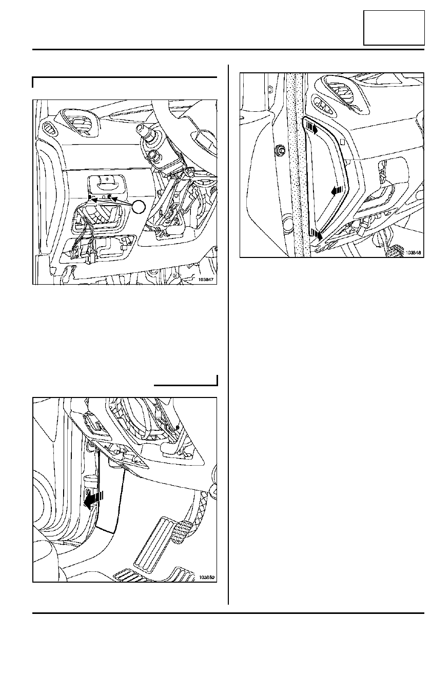
Remove the automatic parking brake catch moun-
ting bolts (13).

Disconnect the automatic parking brake control con-
nector.

Remove the catch.

Unclip the left footwell trim.

Unclip the front left-hand side panel.

AUTOMATIC PARKING BRAKE

103847

103850

13

103848

36B

-

10

POWER ASSISTED STEERING

Steering column

36B

Remove:

- the bolts,

- the lower section of the dashboard,

Remove the air duct.

Unclip the instrument panel upper trim.

103849

103853

104102

103585

36B

-

11

POWER ASSISTED STEERING

Steering column

36B

Unclip the instrument panel lower trim.

Pull back the carpet on the driver's side.

Remove the cover (5) using a hammer. Do not keep
it.

Remove the steering column universal joint bolt.

Remove the column lock bolt (6).

Disconnect the column lock connector.

Remove the column lock.

Disconnect:

- the electric power assisted steering computer

power connector using a screwdriver 4 mm  wide
and 0.5 mm thick,

- the electric power assisted steering computer si-

gnal connector using a screwdriver 4 mm wide and
0.5 mm thick.

Unclip the steering column rotary switch wiring har-
ness (7).

103584

101354

5

104016

Note:

- The column lock is mounted by a left-hand

thread bolt.

WARNING

Do not unclip the clip from the column, this could
break it.

6

7

36B

-

12

POWER ASSISTED STEERING

Steering column

36B

Remove the steering column upper mounting nut (8).

Remove:

- the three steering column mounting lower nuts,

- the steering column.

REFITTING

Proceed in the reverse order to removal.

Refit the steering column, starting with the furthest
lower threaded stud, and finishing with the upper
threaded stud. 

104019

104018

8

WARNING

Push and pull on the electric power assisted 
steering computer power and signal connectors 
to check that they are properly secured (risk of 
loss of assistance).

- The steering wheel should enter the splines

freely (the splines are foolproofed).

- Do not damage the foolproofing splines.

- Be sure to replace the steering wheel bolt each

time it is removed.

Note:

- Be sure to replace the steering column universal

joint bolt and eccentric nut each time they are
removed.

- Do not refit the cover (14).

- On a new steering column, the universal joint

eccentric nut is pre-fitted.


Content   ..  24  25  26  27   ..