Opel Frontera UE. Manual - part 846


  Index      Opel     Opel Frontera UE - service repair manual 1999-2001 year


Search            copyright infringement  


Content   ..  844  845  846  847   ..


Opel Frontera UE. Manual - part 846


6E1–267

X22SE 2.2L ENGINE DRIVEABILITY AND EMISSION

3. Add engine coolant to required level. Refer to Engine

Cooling System Section.

4. Connect the negative battery cable.

0016

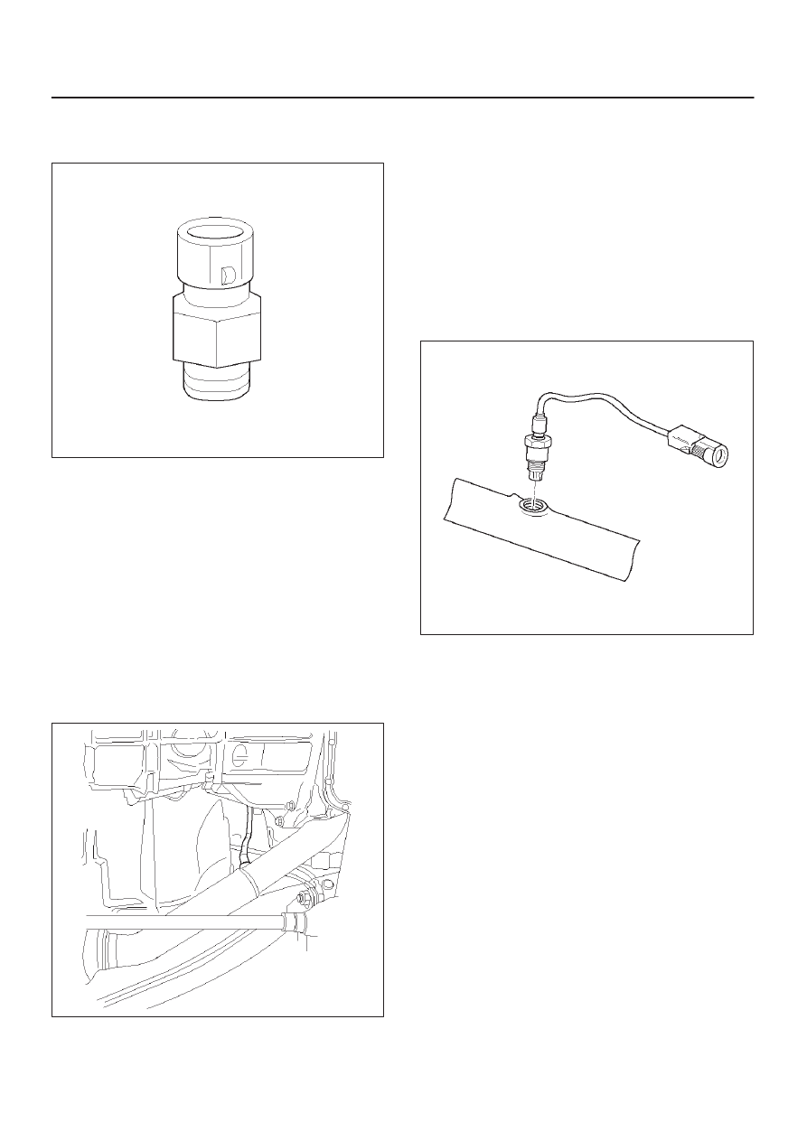
Heated Oxygen Sensor (HO2S)

Removal Procedure

1. Disconnect the negative battery cable.
2. Locate the two oxygen sensors.

D

Bank 1 sensor 1 is mounted on the exhaust pipe
ahead of the catalytic converter.

D

Bank 1 sensor 2 is mounted on the exhaust pipe
behind the catalytic converter.

3. Disconnect pig tail electrical connector.

IMPORTANT:

The pigtail is permanently attached to

the sensor. Be careful not to pull the wires out.

014RX010

4. Unscrew sensors form the exhaust pipe. Because of

the expansion and contraction of the metal in the
exhaust system over time, this may be difficult if the
engine temperature is below 48 degree C.

Inspection Procedure

NOTE: Both sensors are identical. Inspect each inthe
same way.

1. Inspect the pigtail and the electrical connector for

grease, dirt, corrosion and bare wire or worn
insulation.

2. Inspect the louvered end of the sensor for grease,

dirt, excessive carbon build up or other contaminants.

TS23739

Installation Procedure

NOTE: If HO2S is reinstalled after removal, special
anti–seize compound or the equivalent should be applied
to the threads. Special anti–seize compound, (P/N
5613695), is used on the HO2S threads. This compound
consists of glass beads suspended in a liquid graphite
solution. The graphite burns away with exhaust heat, but
the glass beads will remain, making the sensor easier to
remove.

6E1–268

X22SE 2.2L ENGINE DRIVEABILITY AND EMISSION

1. Apply anti–seize compound or the equivalent to the

thread.

TS23739

2. Install HO2S on the exhaust pipe.
3. Tighten the sensor to 55 Nm (5.6 kg·m/40 lb ft)
4. Connect the pig tail to the wiring harness.
5. Connect the negative battery cable.

(Pre–Catalytic Converter Heater Oxygen Sensor Loca-
tion)

014RX010

(Post–Catalytic Converter Heater Oxygen Sensor
Location)

014RX009

Intake Air Temperature (IAT)

Sensor

Removal Procedure

1. Disconnect the negative battery cable.
2. The IAT sensor is located in the intake air duct

between the air filter and the throttle body.

014RX011

6E1–269

X22SE 2.2L ENGINE DRIVEABILITY AND EMISSION

3. Disconnect the electrical connector from the sensor.
4. Remove the sensor from intake air duct by using a

rocking motion while pulling the sensor.

0018

Installation Procedure

1. Install the IAT sensor into intake air duct. Make sure

the sensoris pushed all the way into the intake air
duct.

2. Connect electrical connector.
3. Connect the negative battery cable.

014RX011

Manifold Absolute Pressure

(MAP) Sensor

Removal Procedure

1. Disconnect the negative battery cable.
2. Disconnect the electrical connector from the sensor.

(The MAP sensoris located on the intake manifold
behind throttle body.)

3. Remove a mounting bolt securing the sensor to the

manifold.

4. Remove the sensor from the intake manifold using

rocking motion while pulling the sensor.

014RX012

Installation Procedure

1. Push MAP sensor into the manifold. Make sure the

sensor is pushed always into its position.

2. Install a mounting bolts and tighten.
3. Connect electrical connector.
4. Connect the negative battery cable.

014RX013

Malfunction Indicator Lamp

(MIL)

Malfunction Indicator Lamp (MIL)

Refer to Instrument Panel Removal Procedure.

6E1–270

X22SE 2.2L ENGINE DRIVEABILITY AND EMISSION

Engine Control Module (ECM)

Electrostatic Discharge (ESD) 
Damage

Electronic components used in the control system are
often designed to carry very low voltage. Electronic
components are susceptible to damage caused by
electrostatic discharge. Less than 100 volts of static
electricity can cause damage to same electronic
components. By comparison, it takes as much as 4000
volts for a person to even feel the zap of a static
discharge. There are several way for a person to become
statically charged. The most common methods of
charging are by friction and by induction. An example of
charging by friction is a person sliding across a car seat.
Charging by induction occurs when a person with well
insulated shoes stands near a highly charged object and
momentarily touches ground. Charge of the same polarity
are drained off leaving the person highly charged with
opposite  polarity. Static charge can cause damage,
therefore, it is important to use care when handling and
testing electronic components.

NOTE: To prevent possible Electrostatic Discharge
damage, follow these guidelines:

D

Do not touch the control module connector pins or
soldered components on the control module circuit
board.

D

Do not open the replacement part package until the
part is ready to be installed.

D

Before removing the parts from the package, ground
the package to a known good ground on the vehicle.

D

If the parts been handled while sliding across the
seat, or while sitting from standing position, or walking
a distance, touch a known good ground before
installing the parts.

014RX002

NOTE: To prevent internal ECM damage, the ignition
must be OFF position in order to disconnect or reconnect
power to the ECM (for example: battery cable. pig tail,
ECM fuse, jumper cable, etc.).

IMPORTANT:

When replacing the production ECM

with a service ECM, it is important to transfer the
broadcast code and production ECM number to the
service ECM label. This will allow positive identification of
ECM parts throughout the service life of the vehicle.  Do
not record this information on ECM metal cover.

Removal Procedure

1. Disconnect the negative battery cable.
2. Block the wheels.
3. Remove ashtray inner.
4. Remove a screw located behind ashtray.

014RX014

5. Pull out Face trim of console.
6. Remove two screws located inside of center console

storage box and pull up rear part of center console.

014RX015

7. Unscrew the shift knob.
8. Remove four screw holding front part of the console

and pull the console up.


Content   ..  844  845  846  847   ..