Content .. 1679 1680 1681 1682 ..
Opel Frontera UE. Manual - part 1681
8D–154
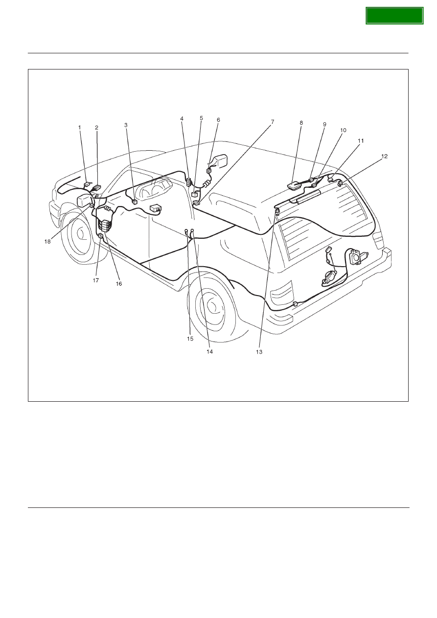
WIRING SYSTEM
Parts Location
D08RY00834
Legend
(1) H–6
(2) E–21, E–22
(3) I–7
(4) H–14, H–19, H–32
(5) Relay & Fuse Box
(6) D–3
(7) H–28
(8) Luggege Room Light
(9) B–11
(10) H–21
(11) H–20
(12) G–9
(13) G–2
(14) B–8
(15) B–6
(16) H–31
(17) H–33
(18) D–12