Content .. 1338 1339 1340 1341 ..
Opel Frontera UE. Manual - part 1340
DRIVE LINE CONTROL SYSTEM (TOD)
4B2–100
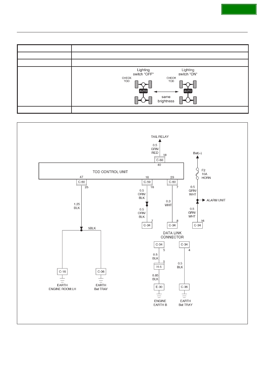
Chart H
Lighting switch circuit
Function of circuit
Reads in the status of lighting switch, and reduces the indicator at night.
Fail condition
Even if the lighting switch is pressed on and off, brightness does not change.
Indicator lamp state
TOD switch position
All position (exsample TOD mode)
D04R100011