Content .. 1337 1338 1339 1340 ..
Opel Frontera UE. Manual - part 1339
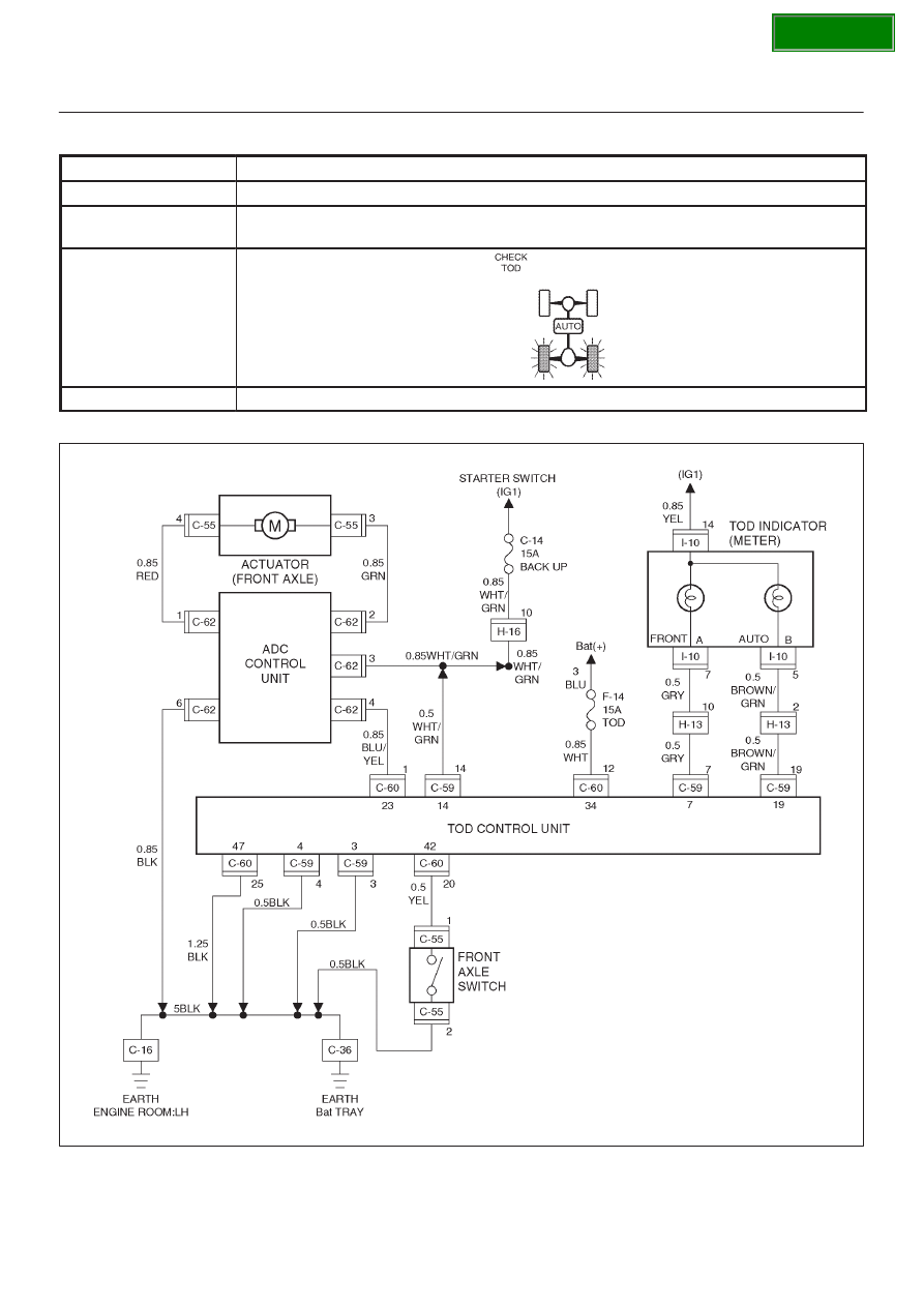
DRIVE LINE CONTROL SYSTEM (TOD)
4B2–96
Chart E–2
The AXLE switch circuit is short-circuited to GND.
Function of circuit
—
Fail condition
Even after the TOD switch is selected to the 2H position, the 2H mode is not enabled.
(The transition status is not removed.)
Indicator lamp state
TOD switch position
2H
D04R100013