Nissan Cube. Manual - part 592
HAC-206
< REMOVAL AND INSTALLATION >
[MANUAL AIR CONDITIONING]
REFRIGERANT PRESSURE SENSOR
REFRIGERANT PRESSURE SENSOR
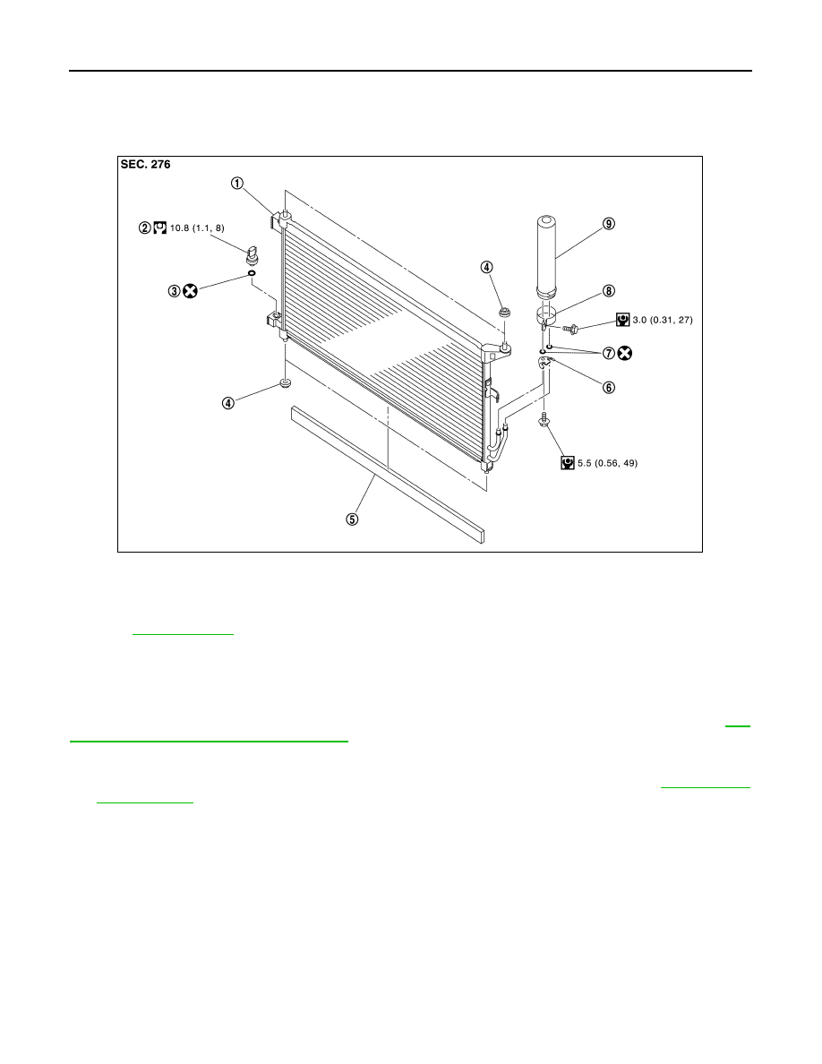
Exploded View
INFOID:0000000009951111
Removal and Installation
INFOID:0000000009951112
CAUTION:
Perform lubricant return operation before each refrigeration system disassembly. However, if a large
amount of refrigerant or lubricant is detected, never perform lubricant return operation. Refer to
26, "Perform Lubricant Return Operation"
REMOVAL
1.
Use a refrigerant collecting equipment (for HFC-134a) to discharge the refrigerant. Refer to
2.
Clean refrigerant pressure sensor and its surrounding area, and then remove dust and rust from refriger-
ant pressure sensor.
CAUTION:
Be sure to clean carefully.
3.
Disconnect refrigerant pressure sensor connector.
1.
Condenser
2.
Refrigerant pressure sensor
3.
O-ring
4.
Grommet
5.
Condenser seal
6.
Bracket
7.
O-ring
8.
Liquid tank bracket
9.
Liquid tank
Refer to
for symbols in the figure.
JPIIA1552GB