Nissan Teana J32. Manual - part 963
 

  Index      Nissan     Nissan Teana J32 (2008 year) - Service and Repair Manual


Search            


Content   ..  961  962  963  964   ..


Nissan Teana J32. Manual - part 963


REAR SUSPENSION ARM

RSU-17

< REMOVAL AND INSTALLATION >

C

D

F

G

H

I

J

K

L

M

A

B

RSU

N

O

P

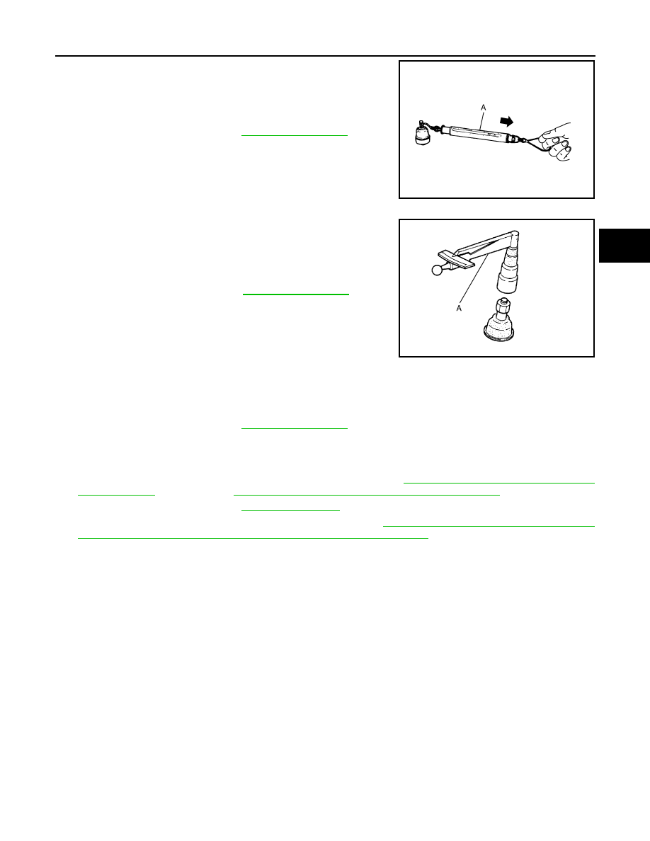
• Hook spring balance (A) at cotter pin mounting hole. Confirm

spring balance measurement value is within specifications when
ball stud begins moving.

• If swing torque exceeds the standard value, replace suspension

arm assembly.

Rotating Torque Inspection

• Attach the mounting nut to ball stud. Make sure that rotating torque

is within the specifications with a preload gauge (A) (SST:
ST3127S000).

- If rotating torque exceeds the standard value, replace suspension

arm assembly.

Axial End Play Inspection

• Move tip of ball stud in axial direction to check for looseness.

- If axial end play exceeds the standard value, replace suspension arm assembly.

INSPECTION AFTER INSTALLATION

1.

Check wheel sensor harness for proper connection. Refer to 

BRC-58, "REAR WHEEL SENSOR :

Exploded View"

 (without VDC), 

BRC-152, "REAR WHEEL SENSOR : Exploded View"

 (with VDC).

2.

Check wheel alignment. Refer to 

RSU-6, "Inspection"

.

3.

Adjust neutral position of steering angle sensor. Refer to 

BRC-66, "ADJUSTMENT OF STEERING

ANGLE SENSOR NEUTRAL POSITION : Special Repair Requirement"

.

Standard

Swing torque

Refer to 

RSU-20, "Ball Joint"

.

JPEIA0005ZZ

Standard

Rotating torque

: Refer to 

RSU-20, "Ball Joint"

.

PDIA1258E

Standard

Axial end play

Refer to 

RSU-20, "Ball Joint"

.

RSU-18

< REMOVAL AND INSTALLATION >

REAR SUSPENSION MEMBER

REAR SUSPENSION MEMBER

Exploded View

INFOID:0000000003811160

Removal and Installation

INFOID:0000000003811161

REMOVAL

1.

Remove tires.

2.

Remove caliper assembly. Hang caliper assembly in a place where it will not interfere with work. Refer to

BR-40, "BRAKE CALIPER ASSEMBLY : Exploded View"

.

3.

Remove wheel sensor and sensor harness. Refer to 

BRC-58, "REAR WHEEL SENSOR : Exploded View"

(without VDC), 

BRC-152, "REAR WHEEL SENSOR : Exploded View"

 (with VDC).

4.

Remove center muffler and main muffler. Refer to 

EX-5, "Exploded View"

.

5.

Remove stabilizer bar. Refer to 

RSU-15, "Exploded View"

.

6.

Separate the attachment between parking brake cable and vehicle and rear suspension member. Refer to

PB-5, "Exploded View"

.

7.

Separate auto levelizer control unit harness connector (with xenon combination lamp type). Refer to 

EXL-

190, "Exploded View"

.

8.

Remove rear lower link and coil spring. Refer to 

RSU-8, "Exploded View"

9.

Remove shock absorber (lower side). Refer to 

RSU-10, "Exploded View"

.

10. Set suitable jack under rear suspension member.

11. Remove member stay (front and rear side).

12. Slowly lower jack, then remove rear suspension member, suspension arm, radius rod, front lower link and

axle housing from vehicle as a unit.

13. Remove the following parts.

• Axle housing: refer to 

RAX-4, "Exploded View"

.

• Auto levelizer control unit (with xenon combination lamp type): refer to 

EXL-190, "Exploded View"

.

• Suspension arm: refer to 

RSU-16, "Exploded View"

.

• Radius rod: refer to 

RSU-12, "Exploded View"

.

• Front lower link: refer to 

RSU-14, "Exploded View"

.

INSTALLATION

Note the following, and install in the reverse order of the removal.

1.

Member stay (rear side)

2.

Rear suspension member

3.

Member stay (front side)

Refer to 

GI-4, "Components"

 for symbols in the figure.

JPEIB0107GB

REAR SUSPENSION MEMBER

RSU-19

< REMOVAL AND INSTALLATION >

C

D

F

G

H

I

J

K

L

M

A

B

RSU

N

O

P

• Perform the final tightening of each of parts under unladen conditions, which were removed when removing

rear suspension assembly.

• After final tightening, install auto levelizer control unit (with xenon combination lamp type). Refer to 

EXL-190,

"Exploded View"

.

• Never reuse cotter pin.

Inspection

INFOID:0000000003811162

INSPECTION AFTER REMOVAL

Check rear suspension member for deformation, cracks, or any other damage. Replace if necessary.

INSPECTION AFTER INSTALLATION

1.

Check wheel sensor harness for proper connection. Refer to 

BRC-58, "REAR WHEEL SENSOR :

Exploded View"

 (without VDC), 

BRC-152, "REAR WHEEL SENSOR : Exploded View"

 (with VDC).

2.

Adjust parking brake operation (stroke). 

PB-2, "Inspection and Adjustment"

.

3.

Check wheel alignment. Refer to 

RSU-6, "Inspection"

.

4.

Adjust neutral position of steering angle sensor. Refer to 

BRC-66, "ADJUSTMENT OF STEERING

ANGLE SENSOR NEUTRAL POSITION : Special Repair Requirement"

.

RSU-20

< SERVICE DATA AND SPECIFICATIONS (SDS) 

SERVICE DATA AND SPECIFICATIONS (SDS)

SERVICE DATA AND SPECIFICATIONS (SDS)

SERVICE DATA AND SPECIFICATIONS (SDS)

Wheel Alignment

INFOID:0000000003811163

Measure value under unladen* conditions.

*: Fuel, engine coolant and lubricant are full. Spare tire, jack, hand tools and mats are in designated positions. 

Ball Joint

INFOID:0000000003811164

Wheel Height

INFOID:0000000003815380

Measure value under unladen* conditions.

*: Fuel, engine coolant and lubricant are full. Spare tire, jack, hand tools and mats are in designated positions.

Item

Standard

Camber
Degree minute (Decimal degree)

Minimum

–0

°

 57

 (–0.95

°

)

Nominal

–0

°

 27

 (–0.45

°

)

Maximum

0

°

 03

 (0.05

°

)

Total toe-in

Distance

Minimum

0 mm (0 in)

Nominal

In 1.6 mm (0.063 in)

Maximum

In 3.2 mm (0.126 in)

Angle (left wheel or right wheel)
Degree minute (Decimal degree)

Minimum

0

°

 00

 (0.00

°

)

Nominal

In 0

°

 04

 (0.07

°

)

Maximum

In 0

°

 08

 (0.13

°

)

Item

Standard

Swing torque

0.5 – 3.4 N·m (0.06 – 0.34 kg-m, 5 – 30 in-lb)

Measurement on spring balance (cotter pinhole position)

8.1 – 54.8 N (0.83 – 5.6 kg, 1.82 – 12.32 lb)

Rotating torque

0.5 – 3.4 N·m (0.06 – 0.34 kg-m, 5 – 30 in-lb)

Axial end play

0 mm (0 in)

Tire size

205/65R16

215/55R17

Engine

VQ25DE

VQ35DE

Grade

250XE

250XL-V6

250XV-V6

350XV-V6

Front (Hf)

712 mm (28.03 in)

711 mm (27.99 in)

710 mm (27.95 in)

Rear (Hr)

703 mm (27.68 in)

702 mm (27.64 in)

701 mm (27.60 in)

SFA818A


Content   ..  961  962  963  964   ..