Nissan Teana J32. Manual - part 723
INL-10
< FUNCTION DIAGNOSIS >
INTERIOR ROOM LAMP BATTERY SAVER SYSTEM
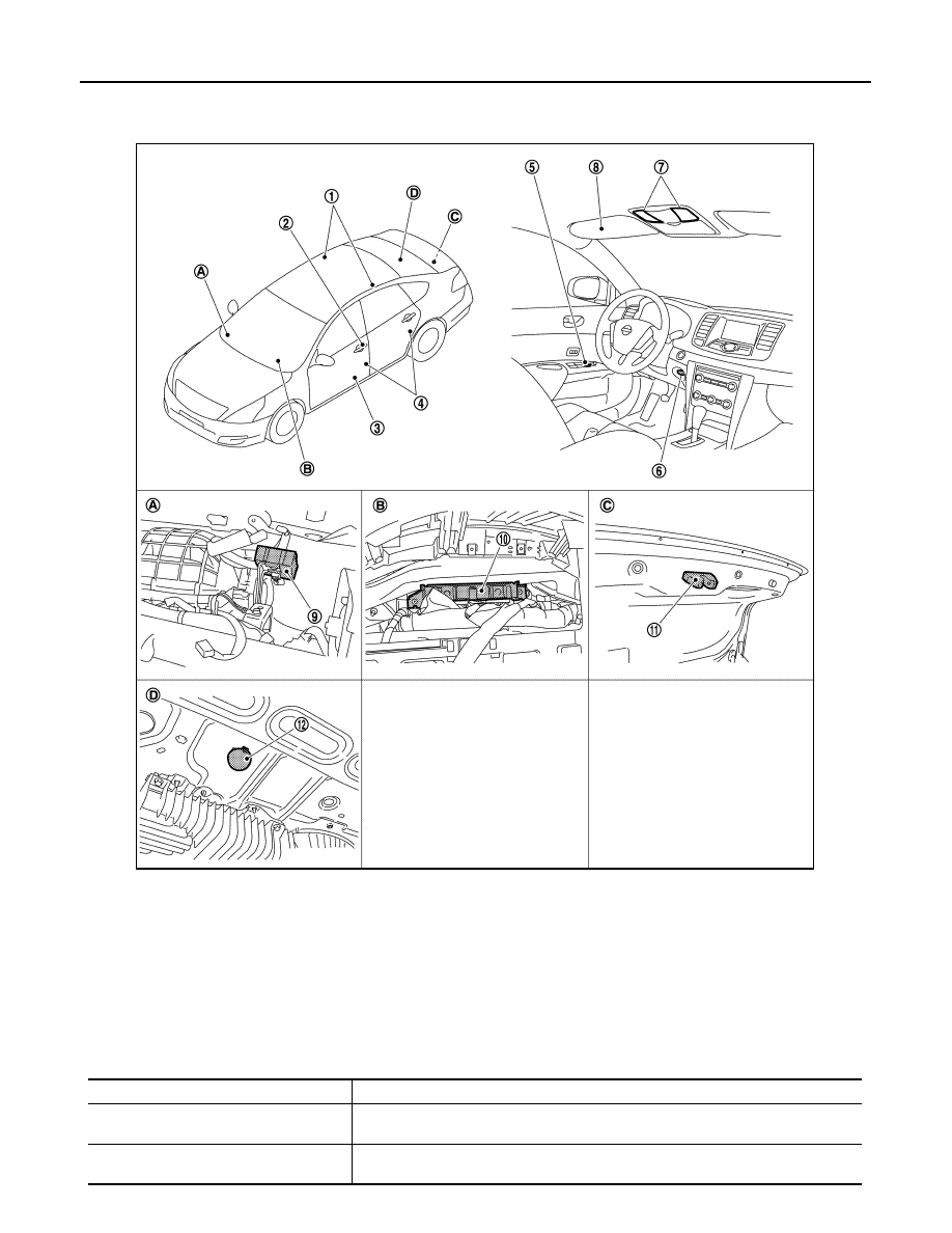
Component Parts Location
INFOID:0000000003774545
Component Description
INFOID:0000000003774546
1.
Personal lamp
2.
Request switch
3.
Step lamp
4.
Door switch
5.
Door lock/unlock switch
6.
Key slot
7.
Map lamp
8.
Vanity mirror lamp
9.
Remote keyless entry receiver
10. BCM
11.
Trunk room lamp switch
12.
Trunk room lamp
A.
Over the glove box
B.
Behind the combination meter
C.
Trunk lid lock assembly
D.
Trunk room upward
JPLIA1127ZZ
Part
Description
BCM
Operates the interior room lamp battery saver depending on the vehicle condition to
cut the interior room lamp power supply.
Remote keyless entry receiver
• Receives the lock/unlock signal from keyfob.
• Transmits the lock/unlock signal to BCM.