Nissan Teana J32. Manual - part 720


  Index      Nissan     Nissan Teana J32 (2008 year) - Service and Repair Manual


Search            


Content   ..  718  719  720  721   ..


Nissan Teana J32. Manual - part 720


HRN-4

< COMPONENT DIAGNOSIS >
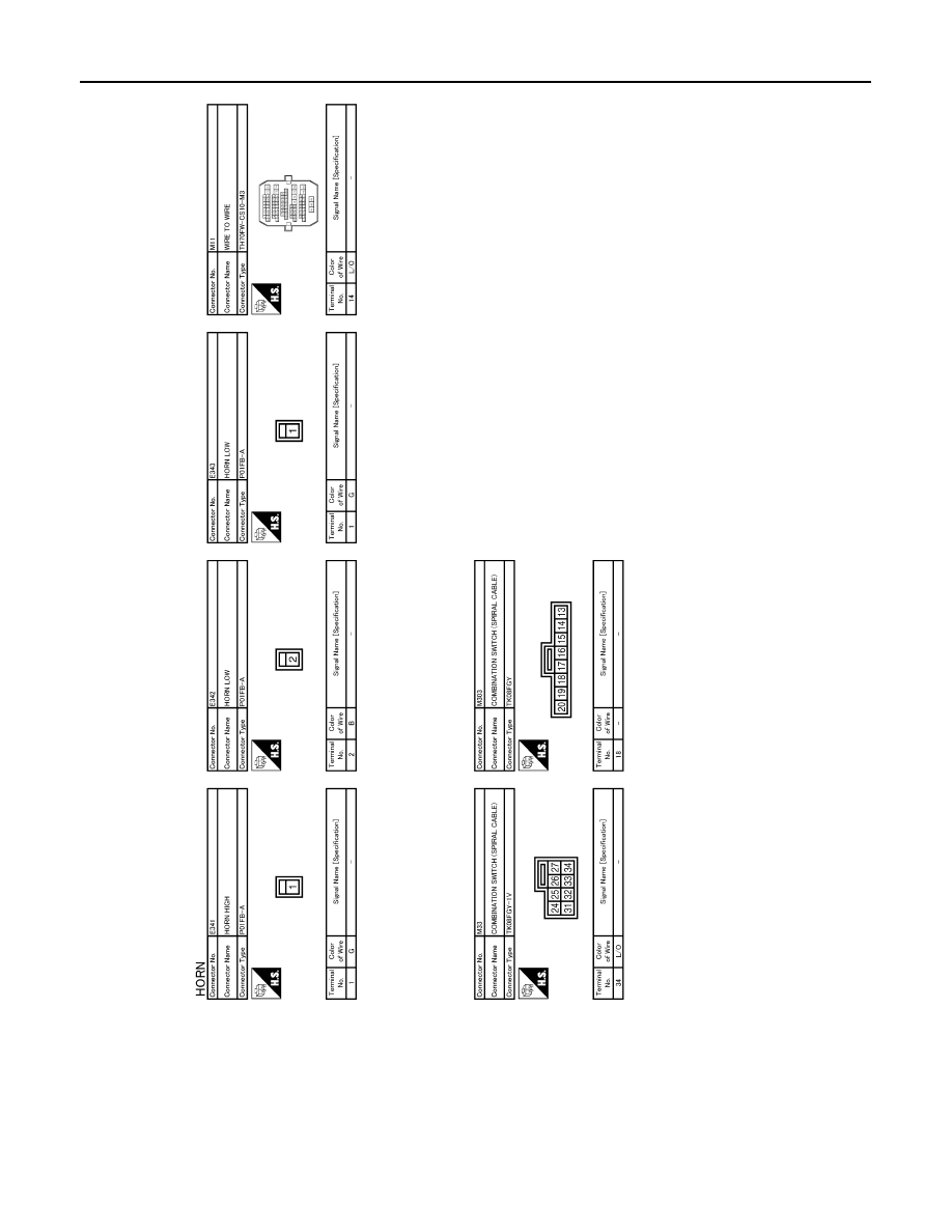
HORN

JCLWM1513GB

PRECAUTIONS

HRN-5

< PRECAUTION >

C

D

E

F

G

H

I

J

K

M

A

B

HRN

N

O

P

PRECAUTION

PRECAUTIONS

Precaution for Supplemental Restraint System (SRS) "AIR BAG" and "SEAT BELT 
PRE-TENSIONER"

INFOID:0000000003761551

The Supplemental Restraint System such as “AIR BAG” and “SEAT BELT PRE-TENSIONER”, used along
with a front seat belt, helps to reduce the risk or severity of injury to the driver and front passenger for certain
types of collision. Information necessary to service the system safely is included in the “SRS AIRBAG” and
“SEAT BELT” of this Service Manual.

WARNING:

• To avoid rendering the SRS inoperative, which could increase the risk of personal injury or death in

the event of a collision which would result in air bag inflation, all maintenance must be performed by
an authorized NISSAN/INFINITI dealer.

• Improper maintenance, including incorrect removal and installation of the SRS, can lead to personal

injury caused by unintentional activation of the system. For removal of Spiral Cable and Air Bag
Module, see the “SRS AIRBAG”.

• Never use electrical test equipment on any circuit related to the SRS unless instructed to in this Ser-

vice Manual. SRS wiring harnesses can be identified by yellow and/or orange harnesses or harness
connectors.

HRN-6

< ON-VEHICLE REPAIR >

HORN

ON-VEHICLE REPAIR

HORN

Exploded View

INFOID:0000000003761552

Removal and Installation

INFOID:0000000003761553

REMOVAL

1.

Disconnect the horn (LOW/HIGH) connector.

2.

Remove the horn mounting bolt, and remove the horn (LOW/HIGH) from the vehicle.

INSTALLATION

Install in the reverse order of removal.

1.

Horn (LOW)

2.

Horn (HIGH)

JPLIA1129ZZ

INL-1

DRIVER CONTROLS

C

D

E

F

G

H

I

J

K

M

SECTION 

INL

A

B

INL

N

O

P

CONTENTS

INTERIOR LIGHTING SYSTEM

BASIC INSPECTION  ....................................

3

DIAGNOSIS AND REPAIR WORKFLOW  ..........

3

Work Flow  .................................................................

3

FUNCTION DIAGNOSIS ...............................

5

INTERIOR ROOM LAMP CONTROL SYSTEM 

.....

5

System Diagram ........................................................

5

System Description  ...................................................

5

Component Parts Location ........................................

7

Component Description ............................................

8

INTERIOR ROOM LAMP BATTERY SAVER 
SYSTEM ..............................................................

9

System Diagram ........................................................

9

System Description  ...................................................

9

Component Parts Location ......................................

10

Component Description ..........................................

10

ILLUMINATION CONTROL SYSTEM ................

12

System Diagram ......................................................

12

System Description  .................................................

12

Component Parts Location ......................................

13

Component Description ...........................................

13

DIAGNOSIS SYSTEM (BCM)  ............................

14

COMMON ITEM  .........................................................

14

COMMON ITEM : CONSULT-III Function (BCM - 
COMMON ITEM) .....................................................

14

INT LAMP  ..................................................................

15

INT LAMP : CONSULT-III Function (BCM - INT 
LAMP) .....................................................................

16

BATTERY SAVER  .....................................................

17

BATTERY SAVER : CONSULT-III Function (BCM 
- BATTERY SAVER)  ...............................................

17

COMPONENT DIAGNOSIS  .........................

19

POWER SUPPLY AND GROUND CIRCUIT  ....

19

BCM ...........................................................................

19

BCM : Diagnosis Procedure  ....................................

19

INTERIOR ROOM LAMP POWER SUPPLY 
CIRCUIT ............................................................

20

Description ...............................................................

20

Component Function Check  ....................................

20

Diagnosis Procedure  ...............................................

20

INTERIOR ROOM LAMP CONTROL CIRCUIT 

...

22

Description ...............................................................

22

Component Function Check  ....................................

22

Diagnosis Procedure  ...............................................

22

STEP LAMP CIRCUIT .......................................

24

Description ...............................................................

24

Component Function Check  ....................................

24

Diagnosis Procedure  ...............................................

24

TRUNK ROOM LAMP CIRCUIT  .......................

26

Description ...............................................................

26

Component Function Check  ....................................

26

Diagnosis Procedure  ...............................................

26

PUSH-BUTTON IGNITION SWITCH ILLUMI-
NATION CIRCUIT  .............................................

28

Description ...............................................................

28

Component Function Check  ....................................

28

Diagnosis Procedure  ...............................................

28

INTERIOR ROOM LAMP CONTROL SYSTEM 

...

30

Wiring Diagram - INTERIOR ROOM LAMP -  ..........

30

ILLUMINATION .................................................

39

Wiring Diagram - ILLUMINATION -  .........................

39

ECU DIAGNOSIS .........................................

53


Content   ..  718  719  720  721   ..