Nissan Teana J32. Manual - part 615
FRONT DRIVE SHAFT
FAX-31
< ON-VEHICLE REPAIR >
C
E
F
G
H
I
J
K
L
M
A
B
FAX
N
O
P
Never reuse dust shield.
3.
Install circular clip.
CAUTION:
Never reuse circular clip.
4.
Apply balance of the specified amount grease to housing assembly.
5.
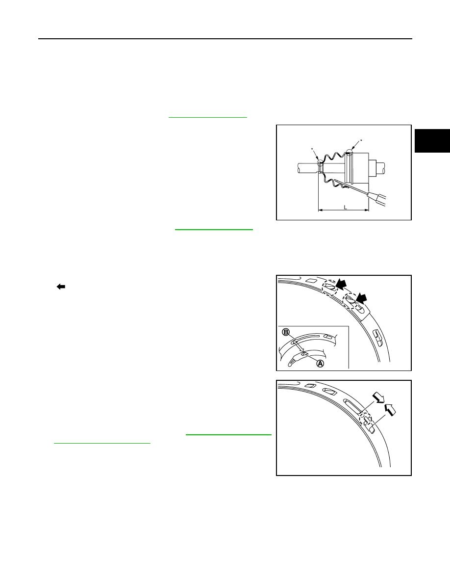
Install boot securely into grooves (indicated by “*” marks) shown
in the figure.
CAUTION:
If grease adheres to the boot mounting surface (indicated
by “*” mark) on housing assembly, boot may be removed.
Remove all grease from the boot mounting surface.
6.
To prevent from deformation of the boot, adjust the boot installa-
tion length (L) by inserting the suitable tool into the inside of boot
from the large diameter side of boot and discharging inside air.
CAUTION:
• If the boot installation length exceeds the standard, it may cause breakage in boot.
• Be careful not to touch the inside of the boot with the tip of tool.
7.
Install boot bands securely as shown in the figure.
a.
Put boot band in the groove on drive shaft boot. Then fit pawls
(
) into holes to temporary installation.
NOTE:
For the large diameter side, fit projection (A) and guide slit (B) at
first.
b.
Pinch projection on the band with suitable pliers to tighten band.
c.
Insert tip of band below end of the pawl.
8.
Secure housing assembly, and then make sure that they are in
the correct position when rotating boot. Reinstall them with boot
bands when the mounting positions become incorrect.
9.
Assemble boot (wheel side). Refer to
.
Right Side
1.
Clean old grease on housing assembly with paper waste.
2.
Install support bearing, follow the procedure described below.
Standard
Grease amount
: Refer to
Standard
L
: Refer to
JPDIF0144ZZ
JPDIF0157ZZ
JPDIF0158ZZ