Content .. 1157 1158 1159 1160 ..
Nissan Teana J32. Manual - part 1159
TM-160
< ON-VEHICLE REPAIR >
[CVT: RE0F09B]
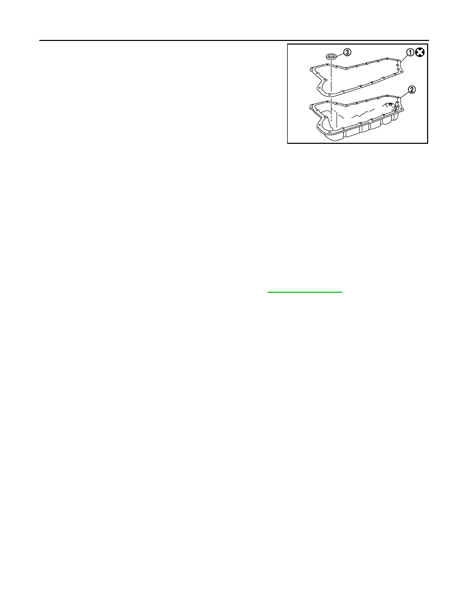
OIL PAN
5.
Remove oil pan gasket (1) from oil pan (2).
6.
Remove magnet (3) from oil pan.
INSTALLATION
Note the following, and install in the reverse order of removal.
CAUTION:
• Completely remove all moisture, oil and old gasket, etc. from the oil pan gasket mounting surface of
transaxle case and oil pan.
• Never reuse oil pan gasket, O-ring and oil pan fitting bolts.
• Apply CVT fluid to O-ring.
Inspection
INFOID:0000000003849096
Check foreign materials in oil pan to help determine causes of malfunction. If the CVT fluid is very dark, smells
burned, or contains foreign particles, frictional material (clutches) may need replacement. A tacky film that will
not wipe clean indicates varnish build up. Varnish can cause valves and clutches to stick and can inhibit pump
pressure.
INSPECTION AFTER INSTALLATION
Check for CVT fluid leakage and check CVT fluid level. Refer to
SCIA8219J