содержание .. 175 176 177 178 ..
Nissan Primera P12. Manual - part 177
COMBINATION METERS (RHD MODELS)
DI-37
C
D
E
F
G
H
I
J
L
M
A
B
DI
Combination Meter Self-Diagnosis
EKS009AS
PERFORMING SELF-DIAGNOSIS MODE
1.
Turn the ignition switch to the “LOCK” position.
2.
Press both reset buttons on the combination meter and keep
them depressed.
3.
Turn the ignition switch to the “ON” position, while keeping the
reset buttons pressed.
4.
Release both reset buttons then self-diagnosis will start. The
sequence (A to L) is activated by press the either reset buttons.
NOTE:
If either reset button is not pressed for 20 seconds at each step
or if the ignition switch is turned OFF, the self-diagnosis mode is
exited.
MKIB0046E
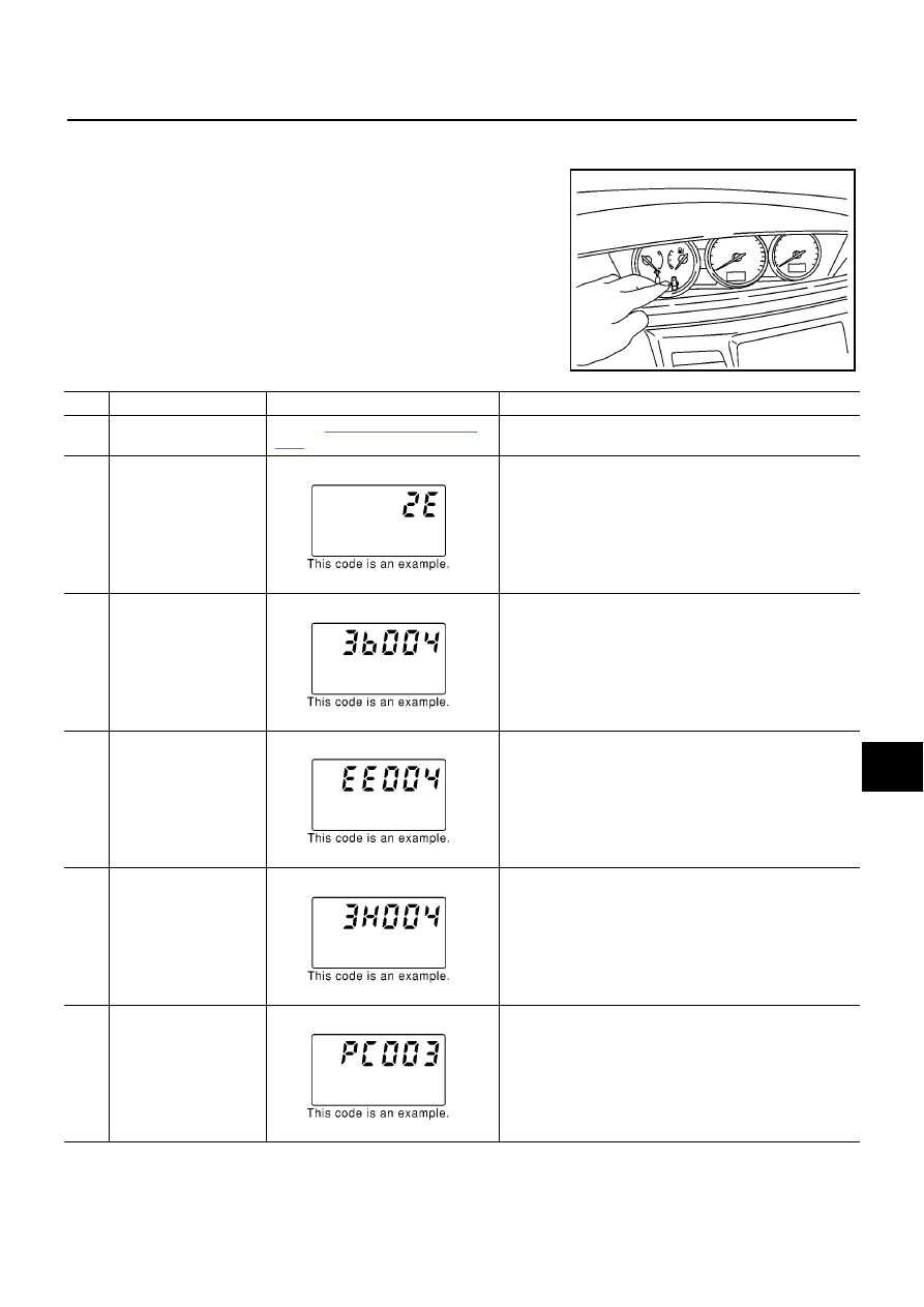
Check items
Display
Remarks
A)
Odometer segment test
Refer to
.
All odo/trip meter, A/T indicator and ICC system display
segments are ON.
B)
Work instruction code
This information is not used for service. Skip this step.
C)
Software code
This information is not used for service. Skip this step.
D)
EEPROM code
This information is not used for service. Skip this step.
E)
Hardware code
This information is not used for service. Skip this step.
F)
PCB code
This information is not used for service. Skip this step.
MKIB0002E
MKIB0003E
MKIB0004E
MKIB0005E
MKIB0006E