содержание .. 728 729 730 731 ..
Nissan Tiida C11. Manual - part 730
EM-272
< ON-VEHICLE REPAIR >
[K9K]
EGR SYSTEM
EGR SYSTEM
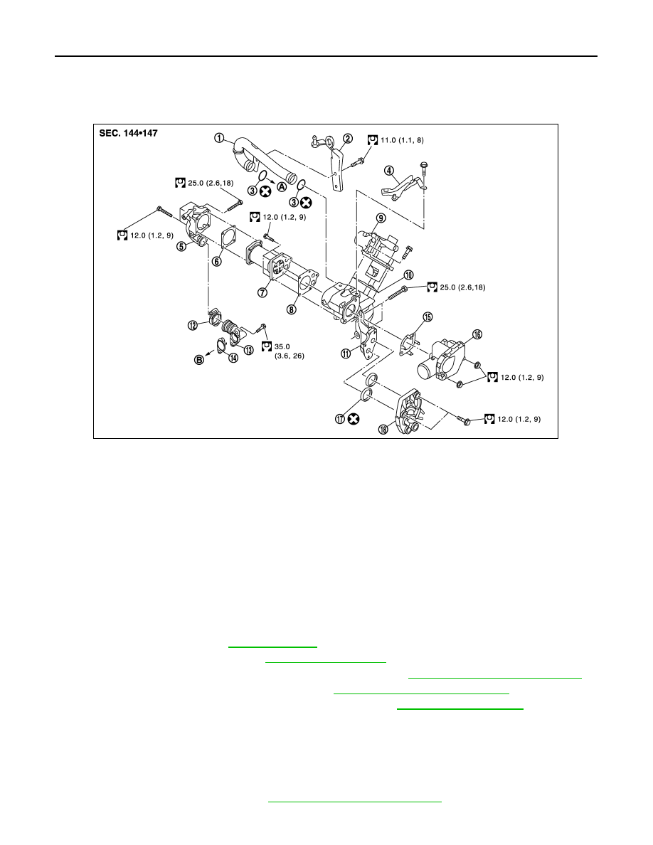
Exploded View
INFOID:0000000001381474
Removal and Installation
INFOID:0000000001381475
REMOVAL
1.
Remove battery ground cable.
2.
Remove engine undercover using power tool.
3.
Drain engine coolant. Refer to
4.
Remove lower radiator hose. Refer to
5.
Remove cowl top cover and cowl top extension assembly. Refer to
EXT-20, "Removal and Installation"
6.
Remove air cleaner and air duct assembly. Refer to
EM-269, "Removal and Installation"
7.
Remove charge air cooler inlet tubes at EGR assembly. Refer to
.
8.
Disconnect EGR volume control valve and electronic throttle control actuator connectors.
9.
Disconnect heater hoses from EGR cooler cover.
10. Remove EGR cooler cover.
11. Remove front engine slinger.
12. Remove air inlet tube.
13. Remove RH fender protector. Refer to
EXT-22, "Removal and Installation"
1.
Air inlet tube
2.
Engine slinger
3.
O-ring
4.
Bracket
5.
EGR tube
6.
Gasket
7.
EGR cooler
8.
Gasket
9.
EGR volume control valve
10. Gasket
11.
EGR volume control valve housing
12. Clamp
13. EGR tube
14. Gasket
15. Gasket
16. Electronic throttle control actuator
17. O-ring
18. EGR cooler cover
A.
To intake manifold
B.
To exhaust manifold
E1BIA0025GB