Nissan Tiida C11. Manual - part 404


  Главная      Nissan     Nissan Tiida C11 - Service Manual


поиск по сайту            


содержание   ..  402  403  404  405   ..


Nissan Tiida C11. Manual - part 404


EC-266

< COMPONENT DIAGNOSIS >

[HR16DE (WITH EURO-OBD)]

P1229 SENSOR POWER SUPPLY

3.

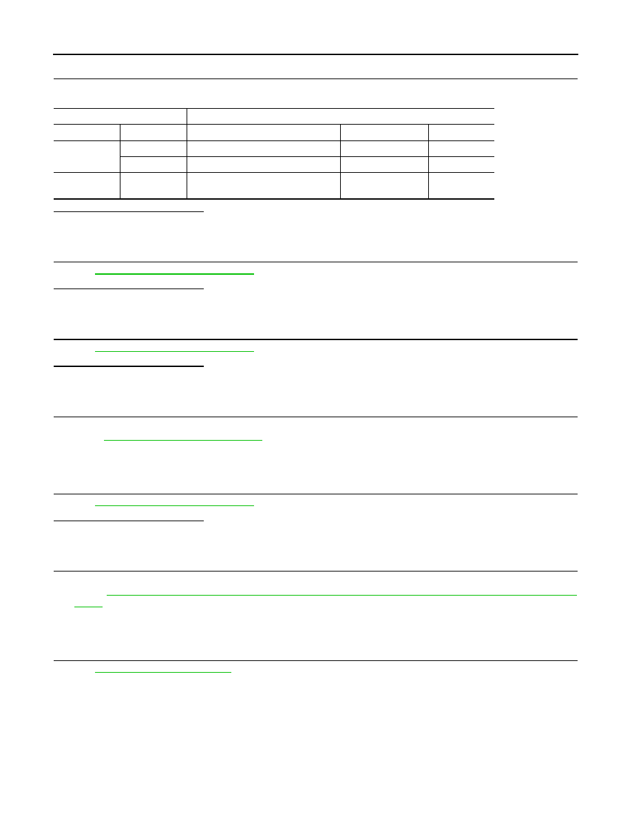
CHECK SENSOR POWER SUPPLY CIRCUITS

Check harness for short to power and short to ground, between the following terminals.

Is the inspection result normal?

YES

>> GO TO 4.

NO

>> Repair short to ground or short to power in harness or connectors.

4.

CHECK COMSHAFT POSITION SENSOR

Refer to 

EC-203, "Component Inspection"

.

Is the inspection result normal?

YES

>> GO TO 5.

NO

>> Replace malfunctioning component.

5.

CHECK TP SENSOR

Refer to 

EC-296, "Component Inspection"

.

Is the inspection result normal?

YES

>> GO TO 7.

NO

>> GO TO 6.

6.

REPLACE ELECTRIC THROTTLE CONTROL ACTUATOR

1.

Replace electric throttle control actuator.

2.

Go to 

EC-296, "Component Inspection"

.

>> INSPECTION END

7.

CHECK APP SENSOR

Refer to 

EC-288, "Component Inspection"

.

Is the inspection result normal?

YES

>> GO TO 9.

NO

>> GO TO 8.

8.

REPLACE ACCELERATOR PEDAL ASSEMBLY

1.

Replace accelerator pedal assembly.

2.

Go to 

EC-26, "ACCELERATOR PEDAL RELEASED POSITION LEARNING : Special Repair Require-

ment"

.

>> INSPECTION END

9.

CHECK INTERMITTENT INCIDENT

Refer to 

GI-55, "Intermittent Incident"

.

>> INSPECTION END

ECM

Sensor

Connector

Terminal

Item

Connector

Terminal

F11

72

Electric throttle control actuator

F7

1

78

CMP sensor (PHASE)

F21

1

E16

106

APP sensor

E12 (LHD models) 

M204 (RHD models)

4

P1564 ASCD STEERING SWITCH

EC-267

< COMPONENT DIAGNOSIS >

[HR16DE (WITH EURO-OBD)]

C

D

E

F

G

H

I

J

K

L

M

A

EC

N

P

O

P1564 ASCD STEERING SWITCH

Description

INFOID:0000000001671042

ASCD steering switch has variant values of electrical resistance for each button. ECM reads voltage variation
of switch, and determines which button is operated.
Refer to 

EC-61, "System Diagram"

 for the ASCD function.

DTC Logic

INFOID:0000000001671043

DTC DETECTION LOGIC

NOTE:
If DTC P1564 is displayed with DTC P0605, first perform the trouble diagnosis for DTC P0605. Refer to

EC-215, "DTC Logic"

.

DTC CONFIRMATION PROCEDURE

1.

PRECONDITIONING

If DTC Confirmation Procedure has been previously conducted, always turn ignition switch OFF and wait at
least 10 seconds before conducting the next test. 

>> GO TO 2.

2.

PERFORM DTC CONFIRMATION PROCEDURE

1.

Turn ignition switch ON.

2.

Wait at least 10 seconds.

3.

Press MAIN switch for at least 10 seconds, then release it and wait at least 10 seconds.

4.

Press CANCEL switch for at least 10 seconds, then release it and wait at least 10 seconds.

5.

Press RESUME/ACCELERATE switch for at least 10 seconds, then release it and wait at least 10 sec-
onds.

6.

Press SET/COAST switch for at least 10 seconds, then release it and wait at least 10 seconds.

7.

Check DTC.

Is DTC detected?

YES

>> Go to 

EC-267, "Diagnosis Procedure"

.

NO

>> INSPECTION END

Diagnosis Procedure

INFOID:0000000001671044

1.

CHECK GROUND CONNECTION

1.

Turn ignition switch OFF.

2.

Check ground connection E15. Refer to Ground Inspection in 

GI-58, "Circuit Inspection"

Is the inspection result normal?

YS

>> GO TO 2.

NO

>> Repair or replace ground connection.

2.

CHECK ASCD STEERING SWITCH CIRCUIT

 With CONSULT-III

1.

Turn ignition switch ON.

DTC No.

Trouble diagnosis 

name

DTC detecting condition

Possible cause

P1564

ASCD steering switch

• An excessively high voltage signal from the 

ASCD steering switch is sent to ECM.

• ECM detects that input signal from the 

ASCD steering switch is out of the specified 
range.

• ECM detects that the ASCD steering switch 

is stuck ON.

• Harness or connectors

(The switch circuit is open or shorted.)

• ASCD steering switch
• ECM

EC-268

< COMPONENT DIAGNOSIS >

[HR16DE (WITH EURO-OBD)]

P1564 ASCD STEERING SWITCH

2.

Select “MAIN SW”, “CANCEL SW”, “RESUME/ACC SW” and “SET SW” in “DATA MONITOR” mode with
CONSULT-III.

3.

Check each item indication under the following conditions.

 Without CONSULT-III

1.

Turn ignition switch ON.

2.

Check the voltage between ECM harness connector terminals as follows.

Is the inspection result normal?

YES

>> GO TO 8.

NO

>> GO TO 3.

3.

CHECK ASCD STEERING SWITCH GROUND CIRCUIT FOR OPEN AND SHORT

1.

Turn ignition switch OFF.

2.

Disconnect ECM harness connector.

3.

Disconnect combination switch harness connector M30.

4.

Check the continuity between combinarion switch and ECM harness connector.

5.

Also check harness for short to ground and short to power.

Is the inspection result normal?

YES

>> GO TO 5.

NO

>> GO TO 4.

4.

DETECT MALFUNCTIONING PART

Check the following.
• Harness connectors M69, E7
• Combination switch (spiral cable)
• Harness for open and short between ECM and combination switch

>> Repair open circuit or short to ground or short to power in harness or connectors.

5.

CHECK ASCD STEERING SWITCH INPUT SIGNAL CIRCUIT FOR OPEN AND SHORT

Monitor item

Condition

Indication

MAIN SW

MAIN switch

Pressed

ON

Released

OFF

CANCEL SW

CANCEL switch

Pressed

ON

Released

OFF

RESUME/ACC SW

RESUME/ACCELERATE switch

Pressed

ON

Released

OFF

SET SW

SET/COAST switch

Pressed

ON

Released

OFF

(+)

(–)

Condition

Voltage

Connector

Terminal

Connector

Terminal

E16

94

(ASCD steering switch signal)

E16

95

MAIN switch: Pressed

Approx. 0V

CANSEL switch: Pressed

Approx. 1V

SET/COAST switch: Pressed

Approx. 2V

RESUME/ACCELERATE switch: Pressed

Approx. 3V

All ASCD steering switches: Released

Approx. 4V

Combination switch

ECM

Continuity

Terminal

Connector

Terminal

15

E16

95

Existed

P1564 ASCD STEERING SWITCH

EC-269

< COMPONENT DIAGNOSIS >

[HR16DE (WITH EURO-OBD)]

C

D

E

F

G

H

I

J

K

L

M

A

EC

N

P

O

1.

Check the continuity between ECM harness connector and combination switch.

2.

Also check harness for short to ground and short to power.

Is the inspection result normal?

YES

>> GO TO 7.

NO

>> GO TO 6.

6.

DETECT MALFUNCTIONING PART

Check the following.
• Harness connectors M69, E7
• Combination switch (spiral cable)
• Harness for open and short between ECM and combination switch

>> Repair open circuit or short to ground or short to power in harness or connectors.

7.

CHECK ASCD STEERING SWITCH

Refer to 

EC-269, "Component Inspection"

.

Is the inspection result normal?

YES

>> GO TO 8.

NO

>> Replace ASCD steering switch.

8.

CHECK INTERMITTENT INCIDENT

Refer to 

GI-55, "Intermittent Incident"

.

>> INSPECTION END

Component Inspection

INFOID:0000000001671045

1.

CHECK ASCD STEERING SWITCH

1.

Disconnect combination switch (spiral cable) harness connector.

2.

Check the continuity between combination switch harness connector terminals under following conditions.

Is the inspection result normal?

YES

>> INSPECTION END

NO

>> Replace ASCD steering switch

Combination switch

ECM

Continuity

Terminal

Connector

Terminal

14

E16

94

Existed

Combination meter

Condition

Resistance

Connector

Terminals

M30

14 and 15

MAIN switch: Pressed

Approx. 0 

CANCEL switch: Pressed

Approx. 250 

SET/COAST switch: Pressed

Approx. 660 

RESUME/ACCELERATE switch: Pressed

Approx. 1,480 

All ASCD steering switches: Released

Approx. 4,000 


содержание   ..  402  403  404  405   ..