Nissan Tiida C11. Manual - part 240


  Главная      Nissan     Nissan Tiida C11 - Service Manual


поиск по сайту            


содержание   ..  238  239  240  241   ..


Nissan Tiida C11. Manual - part 240


DLK-370

< COMPONENT DIAGNOSIS >

[WITH I-KEY & SUPER LOCK]

STOP LAMP SWITCH (M/T)

STOP LAMP SWITCH (M/T)

Diagnosis Procedure

INFOID:0000000001530368

1.

CHECK STOP LAMP SWITCH INPUT SIGNAL

1.

Turn ignition switch OFF.

2.

Disconnect Intelligent Key unit connector.

3.

Check voltage between Intelligent Key unit harness connector
M52 terminal 26 and ground.

Is the inspection result normal?

YES

>> Stop lamp switch is OK.

NO

>> GO TO 2.

2.

CHECK STOP LAMP SWITCH POWER SUPPLY CIRCUIT

1.

Disconnect stop lamp switch connector.

2.

Check voltage between stop lamp switch harness connector
M203 terminal 1 and ground.

Is the inspection result normal?

YES

>> GO TO 3.

NO

>> Repair or replace harness between stop lamp switch

power supply circuit and fuse.
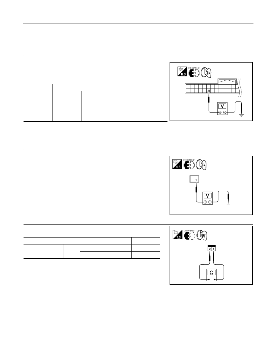
3.

CHECK STOP LAMP SWITCH OPERATION

Check continuity between stop lamp switch terminals 1 and 2.

Is the inspection result normal?

YES

>> GO TO 4.

NO

>> Replace stop lamp switch.

4.

CHECK STOP LAMP SWITCH CIRCUIT

Connector

Terminals

Condition

Voltage (V)

(Approx.)

(+)

(-)

M52

26

Ground

Brake pedal 

depressed

Battery volt-

age

Brake pedal 

released

0

WIIA1207E

1 - Ground

: Battery voltage

WIIA1208E

Component

Terminals

Condition

Continuity

Stop lamp 

switch

1

2

Brake pedal depressed

Yes

Brake pedal released

No

WIIA1209E

STOP LAMP SWITCH (M/T)

DLK-371

< COMPONENT DIAGNOSIS >

[WITH I-KEY & SUPER LOCK]

C

D

E

F

G

H

I

J

L

M

A

B

DLK

N

O

P

1.

Check continuity between Intelligent Key unit harness connector
(A) M52 terminal 26 and stop lamp switch harness connector (B)
M203 terminal 2.

2.

Check continuity between Intelligent Key unit harness connector
M52 terminal 26 and ground.

Is the inspection result normal?

YES

>> Check condition of harness and connector.

NO

>> Repair or replace harness.

26 - 2

: Continuity should exist.

26 - Ground

: Continuity should not exist.

WIIA1210E

DLK-372

< COMPONENT DIAGNOSIS >

[WITH I-KEY & SUPER LOCK]

INTELLIGENT KEY WARNING BUZZER

INTELLIGENT KEY WARNING BUZZER

Description

INFOID:0000000001530361

Answers back and warns about an inappropriate operation. Hatchback vehicles are equipped with a warning
buzzer located inside the driver door. In addition to this buzzer, the sedan vehicles are equipped with a second
buzzer located in the trunk area. 

Component Function Check

INFOID:0000000001530362

1.

CHECK FUNCTION

With CONSULT-III

Check Intelligent Key warning buzzer “OUTSIDE BUZZER” operation in “Active Test” mode.

Does the warning buzzer(s) sound?

YES

>> Intelligent Key warning buzzer(s) is OK.

NO

>> Refer to 

DLK-372, "Diagnosis Procedure"

.

Diagnosis Procedure

INFOID:0000000001530363

1.

CHECK INTELLIGENT KEY WARNING BUZZER(S) POWER SUPPLY CIRCUIT

1.

Turn ignition switch OFF.

2.

Disconnect Intelligent Key warning buzzer connector.

3.

Check voltage between Intelligent Key warning buzzer connec-
tor and ground.

*: Sedan only

Is the inspection result normal?

YES

>> GO TO 2.

NO

>> Repair or replace Intelligent Key warning buzzer power supply circuit.

2.

CHECK HARNESS CONTINUITY

NOTE:
For sedan vehicles, ensure both Intelligent Key warning buzzers are disconnected before proceeding.
1.

Disconnect Intelligent Key unit connector.

PIIB6622E

Terminal

Voltage (V)

(Approx.)

(+)

(–)

Intelligent Key warning buzzer 

connector

Terminal

D6 (driver door)

1

Ground

Battery voltage

B82 (trunk)

*

INTELLIGENT KEY WARNING BUZZER

DLK-373

< COMPONENT DIAGNOSIS >

[WITH I-KEY & SUPER LOCK]

C

D

E

F

G

H

I

J

L

M

A

B

DLK

N

O

P

2.

Check continuity between Intelligent Key unit connector and
Intelligent Key warning buzzer connector.

*: Sedan only

3.

Check continuity between Intelligent Key warning buzzer connector and ground.

Is the inspection result normal?

YES

>> GO TO 3.

NO

>> Repair or replace harness between Intelligent Key warning buzzer and Intelligent Key unit.

3.

CHECK INTELLIGENT KEY WARNING BUZZER

Check Intelligent Key warning buzzer.
Refer to 

DLK-373, "Component Inspection"

.

Is the inspection result normal?

YES

>> GO TO 4.

NO

>> Replace Intelligent Key warning buzzer. Refer to 

XX-XX, "*****"

.

4.

CHECK INTERMITTENT INCIDENT

Refer to @@@.

>> INSPECTION END

Component Inspection

INFOID:0000000001530364

1.

CHECK INTELLIGENT KEY WARNING BUZZER

Connect battery power supply to Intelligent Key warning buzzer ter-
minals 1 and 2, and check the operation.

PIIB6623E

Intelligent Key unit 

connector

Terminal

Intelligent Key warning buzzer 

connector

Terminal

Continuity 

M52

4

Driver door

D6

2

Yes

Trunk

*

B82

Intelligent Key unit 

connector

Terminal

Ground

Continuity 

M52

4

No

PIIB6624E


содержание   ..  238  239  240  241   ..