Nissan Tiida C11. Manual - part 1296


  Главная      Nissan     Nissan Tiida C11 - Service Manual


поиск по сайту            


содержание   ..  1294  1295  1296  1297   ..


Nissan Tiida C11. Manual - part 1296


DISASSEMBLY

TM-235

< DISASSEMBLY AND ASSEMBLY >

[TYPE 1 (4AT: RE4F03B)]

C

E

F

G

H

I

J

K

L

M

A

B

TM

N

O

P

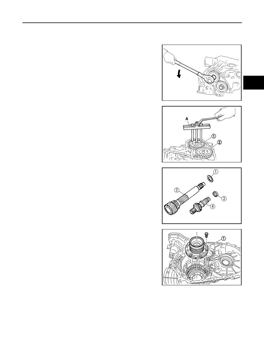
47. Remove output shaft, output gear and reduction gear according to the following procedures.

a.

Set manual shaft in “P” position to fix idler gear and output gear.

b.

Unlock both idler gear and output gear lock nuts using a pin punch.

c.

Remove idler gear and output gear lock nuts.

d.

Remove idler gear (2) and output gear (1) using Tool A.

e.

Remove reduction pinion gear and output shaft from transaxle
case.

f.

Remove reduction pinion gear adjusting shim (1) from reduction
pinion gear (2).

g.

Remove output gear adjusting spacer (3) from output shaft (4).

48. Remove bearing retainer fitting bolts, and then remove bearing

retainer (1) from transaxle case.

SAT704D

Tool number:

ST27180001

SCIA6991E

SCIA5902J

SCIA5909J

TM-236

< DISASSEMBLY AND ASSEMBLY >

[TYPE 1 (4AT: RE4F03B)]

DISASSEMBLY

49. Remove return spring (2) from parking shaft (3) suitable tool.

(1): Parking pawl
• Inspect return spring (2), and replace if damaged or worn.

50. Draw out parking shaft (1), and then remove parking pawl (2)

from transaxle case.
• Inspect parking shaft (1) and parking pawl (2), and replace

if damaged or worn.

51. Remove parking actuator support (1) from transaxle case.

• Inspect parking actuator support (1), and replace if dam-

aged or worn.

52. Remove snap ring from transaxle case using suitable tool.

53. Remove governor cap from transaxle case.

54. Remove O-ring from governor cap.

55. Remove LH differential side oil seal from transaxle case using

suitable tool.

CAUTION:

Do not scratch transaxle case.

SCIA6996E

SCIA6997E

SCIA6998E

ATM0076D

REPAIR FOR COMPONENT PARTS

TM-237

< DISASSEMBLY AND ASSEMBLY >

[TYPE 1 (4AT: RE4F03B)]

C

E

F

G

H

I

J

K

L

M

A

B

TM

N

O

P

REPAIR FOR COMPONENT PARTS

Manual Shaft

INFOID:0000000001730983

COMPONENTS

REMOVAL

1.

Remove detent spring from transaxle case.

2.

Drive out retaining pin of manual plate using suitable tool.

1.

Manual shaft oil seal

2.

Parking rod

3.

Retaining pin

4.

Parking rod plate

5.

Retaining pin

6.

Manual plate

7.

Manual shaft

8.

Detent spring

9.

Retaining pin

SCIA5907J

SAT313G

SAT076D

TM-238

< DISASSEMBLY AND ASSEMBLY >

[TYPE 1 (4AT: RE4F03B)]

REPAIR FOR COMPONENT PARTS

3.

Pull out retaining pin (2) of parking rod plate (1) using suitable
tool.

4.

Pull out retaining pin (1) of manual shaft using suitable tool.

5.

Remove parking rod plate (with parking rod) (3) from manual
shaft (1).

6.

Remove parking rod from parking rod plate (3).

7.

Remove manual plate (2) from manual shaft (1).

8.

Draw out manual shaft (1) from transaxle case.

9.

Remove manual shaft oil seal from transaxle case using suitable
tool.

CAUTION:

Do not scratch transaxle case.

INSPECTION

Check component parts, and replace if damaged or worn.

INSTALLATION

SCIA5806J

SCIA6514J

SCIA7005E

SAT080D


содержание   ..  1294  1295  1296  1297   ..