содержание .. 26 27 28 29 ..
Nissan Tiida C11. Manual - part 28
AV-106
< ECU DIAGNOSIS >
[AUDIO WITH NAVIGATION]
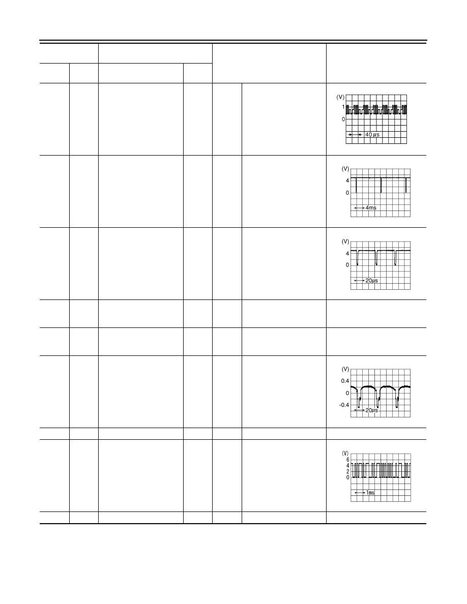
DISPLAY UNIT
5
(W)
8
(B)
RGB signal (B: blue)
Input
Ignition
switch
ON
Start “Confirmation / Adjust-
ment Mode”, and then dis-
play color bar by
selecting“Color Spectrum
Bar” on DISPLAY DIAGNO-
SIS screen.
6
(W)
Ground
Vertical synchronizing (VP)
signal
Output
Ignition
switch
ON
—
7
(B)
Ground
RGB synchronizing signal
Input
Ignition
switch
ON
—
8
(B)
Ground
RGB ground
—
Ignition
switch
ON
—
0 V
10
Ground
Shield
—
Ignition
switch
ON
—
0 V
11
(R)
Ground
Camera image signal
Input
Ignition
switch
ON
At rear view camera image
displayed
12
—
Shield
—
—
—
—
17
(O)
Ground
Communication signal
(DISP
→
CONT)
Output
Ignition
switch
ON
When adjusting display-
brightness.
18
—
Shield
—
—
—
—
Terminal
(Wire color)
Description
Condition
Reference value
(Approx.)
+
–
Signal name
Input/
Output
JPNIA0223ZZ
SKIB0823E
SKIB0825E
SKIB0827E
PKIB5039J