Mitsubishi Outlander GS45X. Manual - part 521
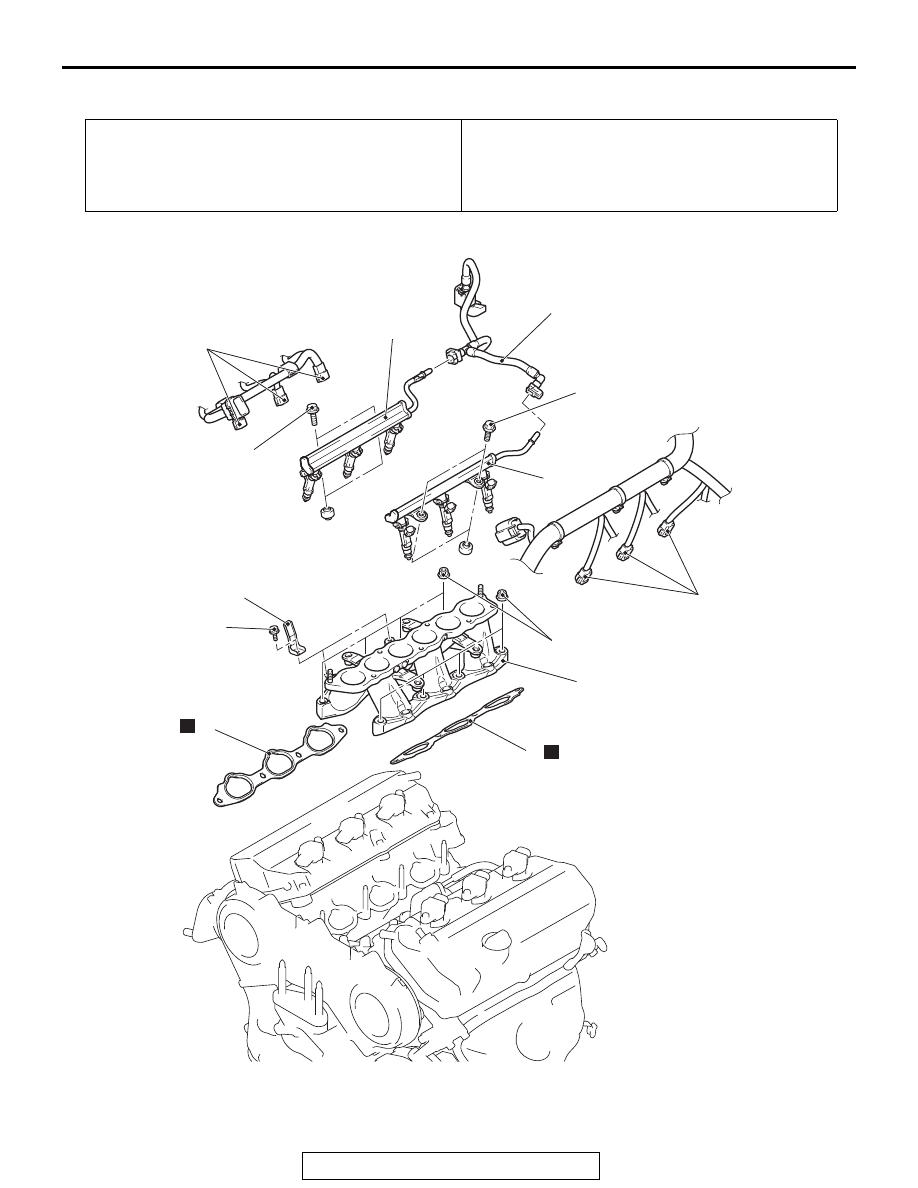
INTAKE MANIFOLD
TSB Revision
INTAKE AND EXHAUST
15-11
REMOVAL AND INSTALLATION <3.0L ENGINE>
M1151003004581
Pre-removal Operation
• Fuel Discharge Prevention [Refer to GROUP 13B,
On-vehicle Service
− Fuel Pump Connector Disconnec-
tion (How to Reduce Pressurized Fuel Lines)
].
• Intake Manifold Plenum Removal (Refer to
Post-installation Operation
• Intake Manifold Plenum Installation (Refer to
• Fuel Leakage Inspection
ACA02243
12 ± 1 N·m
106 ± 8 in-lb
12 ± 1 N·m
106 ± 8 in-lb
11 ± 1 N·m
98 ± 8 in-lb
22 ± 1 N·m
16 ± 1 ft-lb
1
1
2
3
4
5
6
7
7
N
N
AB