Mitsubishi Outlander GS45X. Manual - part 520
INTAKE MANIFOLD PLENUM <3.0L ENGINE>
TSB Revision
INTAKE AND EXHAUST
15-7
AC809105AB
19
18
17
16
15
14
13
12
20
21
N
N
N
11 ± 1 N·m
97 ± 8 in-lb
23 ± 6 N·m
17 ± 4 ft-lb
22 ± 1 N·m
16 ± 1 ft-lb
22 ± 1 N·m
16 ± 1 ft-lb
23 ± 6 N·m
17 ± 4 ft-lb
11 ± 1 N·m
97 ± 8 in-lb
11 ± 1 N·m
97 ± 8 in-lb
11 ± 1 N·m
97 ± 8 in-lb
23 ± 6 N·m
17 ± 4 ft-lb
23 ± 6 N·m
17 ± 4 ft-lb
23 ± 6 N·m
17 ± 4 ft-lb
23 ± 6 N·m
17 ± 4 ft-lb
11 ± 1 N·m
97 ± 8 in-lb
22 ± 1 N·m
16 ± 1 ft-lb
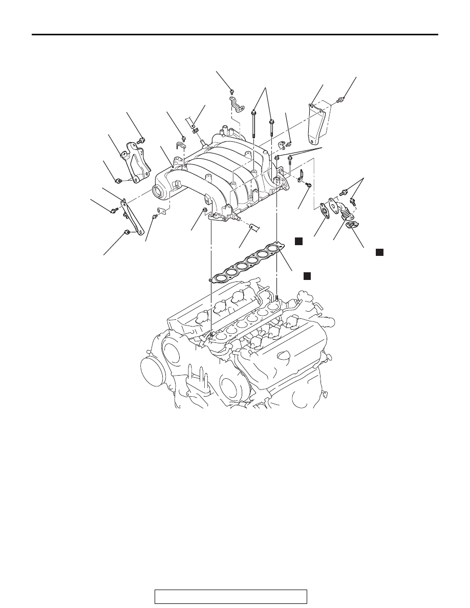
Removal steps
12. PCV hose connection
13. Brake booster vacuum hose
connection
14. Throttle body stay
15. Intake manifold plenum stay (rear)
16. Intake manifold plenum stay (front)
17. EGR pipe
18. EGR pipe gasket
19. EGR pipe gasket
20. Intake manifold plenum
21. Intake manifold plenum gasket
Removal steps (Continued)