Mitsubishi Montero Sport (2004+). Manual - part 639


  Index      Mitsubishi     Mitsubishi Montero Sport - service repair manual 2004 year


Search            


Content   ..  637  638  639  640   ..


Mitsubishi Montero Sport (2004+). Manual - part 639


AUTOMATIC TRANSMISSION DIAGNOSIS

TSB Revision

AUTOMATIC TRANSMISSION

23A-121

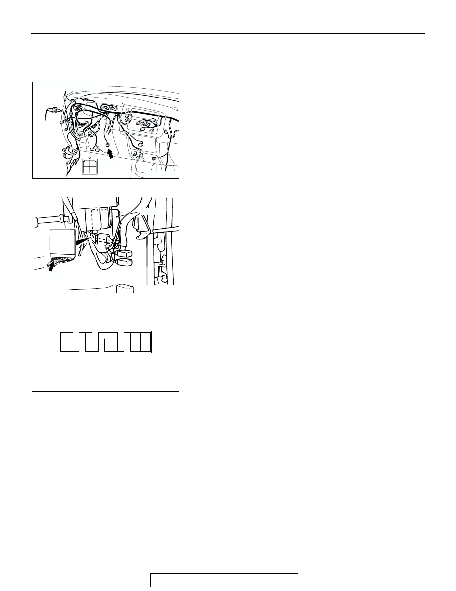
STEP 11. Check the harness for damage between stoplight 
switch connector C-66 terminal 3 and PCM connector C-92 
terminal 123.

Q: Is the harness wire in good condition?

YES : Go to Step 12.
NO :  Repair or replace the harness wire.

AC309389

CONNECTOR: C-66

C-66 (B)

AB

1
3 4

2

AC202317

PCM

120

107

119

106

129 130

118

105

117

114115116

126127128

104

111

103

112

108

101102

109110

121122123

124

113

125

CONNECTOR: C-92

C-92 (GR)

AB

AUTOMATIC TRANSMISSION DIAGNOSIS

TSB Revision

AUTOMATIC TRANSMISSION

23A-122

STEP 12. Using scan tool MB991958, check data list item 
26: Stoplight Switch.

CAUTION

To prevent damage to scan tool MB991958, always turn the 
ignition switch to the "LOCK" (OFF) position before con-
necting or disconnecting scan tool MB991958.
(1) Connect scan tool MB991958 to the data link connector.
(2) Turn the ignition switch to the "ON" position.
(3) Set scan tool MB991958 to data reading mode.

• Item 26: Stoplight Switch.

• When the brake pedal is depressed, the display on 

scan tool MB991958 should be "ON."

• When the brake pedal is not depressed, the display 

on scan tool MB991958 should be "OFF."

(4) Turn the ignition switch to the "LOCK" (OFF) position.
Q: Is the switch operating properly?

YES : It can be assumed that this malfunction is intermittent. 

Refer to GROUP 00E, How to Use 
Troubleshooting/Inspection Service Points 

− How to 

Cope with Intermittent Malfunction 

P.00-7

.

NO :  Replace the PCM.

AK303629AB

MB991911

MB991827

MB991824 

16-PIN

AUTOMATIC TRANSMISSION DIAGNOSIS

TSB Revision

AUTOMATIC TRANSMISSION

23A-123

DTC 27 (P0705): Transmission Range Switch System (Open Circuit)

Transmission Range Switch System Circuit

AC309397

AUTOMATIC TRANSMISSION DIAGNOSIS

TSB Revision

AUTOMATIC TRANSMISSION

23A-124

.

CIRCUIT OPERATION

• Battery positive voltage is applied to the transmis-

sion range switch (terminal 7) when the ignition 
switch is turned "ON."

• Battery positive voltage is applied to the PCM 

(terminal 101) when the selector lever is in the 
"P" range. The PCM judges that the selector 
lever is in the "P" range when the battery positive 
voltage is applied.

• Battery positive voltage is applied to the PCM ter-

minal 108 (121, 102, 109, 122 or 110) when the 
selector lever is in the "R" range ("N," "D," "3," "2" 
or "L" range). The PCM judges that the selector 
lever is in the "R" range ("N," "D," "3," "2" or "L" 
range) when the battery positive voltage is 
applied.

.

AC202393

4
9

5

10

3
8

2
7

6

1

CONNECTOR: B-01
<RWD>

<4WD>

B-01 (B)

B-01 (B)

AB

AC202392

4

3

10 11

9

8

5

12

1
6

2
7

22

9 10

20

19

6 7 8

21

17

1516

5

14

12 13

3

2

4

18

11

1

49

48

50

46

45

44

41 42 43

47

CONNECTORS: C-03, C-30, C-96

C-96

C-30

C-03

C-96

C-30

C-03

AB

AC202317

PCM

120

107

119

106

129 130

118

105

117

114115116

126127128

104

111

103

112

108

101102

109110

121122123

124

113

125

CONNECTOR: C-92

C-92 (GR)

AB

AC202365

JUNCTION BLOCK (REAR)

2

1

M

4

3

19 20

6

17

7

5

15

14

16

8

18

3

11 12

4

2

10

1

9

13

CONNECTORS: D-08, D-13

AB

D-08

D-13

D-08

D-13


Content   ..  637  638  639  640   ..