Mitsubishi Montero Sport (2004+). Manual - part 637


  Index      Mitsubishi     Mitsubishi Montero Sport - service repair manual 2004 year


Search            


Content   ..  635  636  637  638   ..


Mitsubishi Montero Sport (2004+). Manual - part 637


AUTOMATIC TRANSMISSION DIAGNOSIS

TSB Revision

AUTOMATIC TRANSMISSION

23A-113

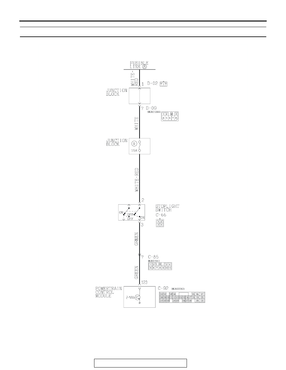
DTC 26: Stoplight Switch System

Stoplight Switch System Circuit

AC309388

AUTOMATIC TRANSMISSION DIAGNOSIS

TSB Revision

AUTOMATIC TRANSMISSION

23A-114

.

AC309389

CONNECTOR: C-66

C-66 (B)

AB

1
3 4

2

AC202389

11

4

3

9

8

10

5 6

2

1

7

CONNECTOR: C-85

C-85

AB

AC202317

PCM

120

107

119

106

129 130

118

105

117

114115116

126127128

104

111

103

112

108

101102

109110

121122123

124

113

125

CONNECTOR: C-92

C-92 (GR)

AB

AC202390

JUNCTION BLOCK (FRONT)

1

D-02 (GR)

AB

CONNECTOR: D-02

AC202391

JUNCTION BLOCK (REAR)

7 8

2

3

6

5

1

4

CONNECTOR: D-09

D-09

AB

AUTOMATIC TRANSMISSION DIAGNOSIS

TSB Revision

AUTOMATIC TRANSMISSION

23A-115

CIRCUIT OPERATION

• Battery positive voltage is supplied to the stop-

light switch (terminal 2).

• When the brake pedal is depressed, battery posi-

tive voltage is applied to the PCM (terminal 123).

.

DTC SET CONDITIONS
If the stoplight switch is on for five minutes or more 
while driving above 50 km/h (31 mph), or all of the 
stop light bulbs are blown, it is judged there is a short 
circuit or open circuit in the stoplight switch. This 
causes DTC 26 to be set.

.

TROUBLESHOOTING HINTS (The most likely 
causes for this code to be set are:)

• Malfunction of the stoplight switch circuit

• Malfunction of stoplight bulb

• Damaged harness, connector

• Malfunction of the PCM

DIAGNOSIS

Required Special Tool:

• MB991958: Scan Tool (MUT-III Sub Assembly)

• MB991824: V.C.I.

• MB991827: MUT-III USB Cable

• MB991911: MUT-III Main Harness B

STEP 1. Check the brake pedal height.

Refer to GROUP 35A, On-vehicle Service 

− Brake Pedal 

Check and Adjustment 

P.35A-15

.

Q: Is the height adjusted properly?

YES : Go to Step 2.
NO :  Adjust the brake pedal to the proper height.

STEP 2. Check the stoplight bulb.

Refer to GROUP 54A, Rear combination light 

P.54-160

.

Q: Is the stoplight bulb in good condition?

YES : Go to Step 3.
NO :  Replace the stoplight switch. Refer to GROUP 35A, 

Brake Pedal 

P.35A-27

.

AUTOMATIC TRANSMISSION DIAGNOSIS

TSB Revision

AUTOMATIC TRANSMISSION

23A-116

STEP 3. Using scan tool MB991958, check data list item 26: 
Stoplight Switch.

CAUTION

To prevent damage to scan tool MB991958, always turn the 
ignition switch to the "LOCK" (OFF) position before con-
necting or disconnecting scan tool MB991958.
(1) Connect scan tool MB991958 to the data link connector.
(2) Turn the ignition switch to the "ON" position.
(3) Set scan tool MB991958 to data reading mode.

• Item 26: Stoplight Switch.

• When the brake pedal is depressed, the display on 

scan tool MB991958 should be "ON."

• When the brake pedal is not depressed, the display 

on scan tool MB991958 should be "OFF."

(4) Turn the ignition switch to the "LOCK" (OFF) position.
Q: Is the switch operating properly?

YES : It can be assumed that this malfunction is intermittent. 

Refer to GROUP 00, How to Use 
Troubleshooting/Inspection Service Points 

− How to 

Cope with Intermittent Malfunction 

P.00E-2

.

NO :  Go to Step 4.

STEP 4. Measure the stoplight switch power supply 
voltage at connectors C-66 by backprobing.

(1) Remove the stoplight switch from the mounting bracket.
(2) Do not disconnect connector C-66.

(3) Measure the voltage between terminal 2 and ground by 

backprobing.

• The voltage should measure battery positive voltage.

Q: Is the measured voltage battery positive voltage?

YES : Go to Step 7.
NO :   Go to step 5.

AK303629AB

MB991911

MB991827

MB991824 

16-PIN

AC309389

CONNECTOR: C-66

C-66 (B)

AB

1
3 4

2

AC203804

1
2

2
4

1

3

AC

C-66 HARNESS 
CONNECTOR:
HARNESS SIDE


Content   ..  635  636  637  638   ..