Mitsubishi Montero Sport (2004+). Manual - part 414


  Index      Mitsubishi     Mitsubishi Montero Sport - service repair manual 2004 year


Search            


Content   ..  412  413  414  415   ..


Mitsubishi Montero Sport (2004+). Manual - part 414


INNER SHAFT ASSEMBLY

TSB Revision

FRONT AXLE

26-37

 DISASSEMBLY AND ASSEMBLY

M1261004200089

Required Special Tools:

• MB990955: Oil Seal Installer

• MB990560: Bearing Remover

• MB990938: Brass Bar

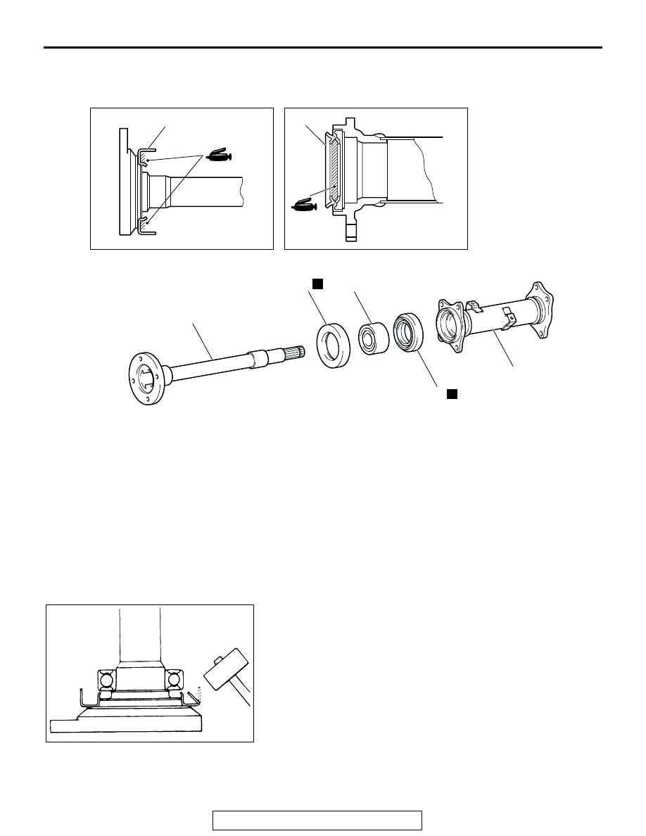
DISASSEMBLY SERVICE POINT

.

<<A>> BEARING REMOVAL
1. Bend the outside periphery of dust cover inward with a 

wooden hammer.

AC103695

5

3

1

2

3

N

5

N

4

AB


DISASSEMBLY 

STEPS


1. INNER 

SHAFT

<<A>> >>C<<

2. BEARING


>>B<<

3.

DUST COVER


4. HOUSING 

TUBE


>>A<<

5. DUST 

SEAL


DISASSEMBLY STEPS (Continued)

ACX01002AB

INNER SHAFT ASSEMBLY

TSB Revision

FRONT AXLE

26-38

2. After special tool MB990560 has been installed as shown, 

tighten the nut of the special tool until the portion of the 
special tool  touches the bearing outer race.

3. Press out the inner shaft from the bearing.

ASSEMBLY SERVICE POINTS

.

>>A<< DUST SEAL INSTALLATION
Press-fit the new dust seal into the housing tube by using spe-
cial tools MB990938 and MB990955, until it is flush with the 
housing tube end face.

.

>>B<< DUST COVER INSTALLATION
Using a steel pipe, install a new dust cover onto the inner shaft.

.

ACX01003 AB

A

MB990560

ACX01013 AB

MB990560

ACX01014 AB

MB990955

MB990938

STEEL PIPE

mm (in)

Overall length

50 (2.0)

Outside diameter

75 (3.0)

Wall thickness

4 (0.16)

ACX01015 AB

STEEL PIPE

INNER SHAFT ASSEMBLY

TSB Revision

FRONT AXLE

26-39

>>C<< BEARING INSTALLATION
Use special tool MB990560 to press-fit the bearing onto the 
inner shaft.

ACX01016AB

MB990560

DIFFERENTIAL CARRIER ASSEMBLY

TSB Revision

FRONT AXLE

26-40

DIFFERENTIAL CARRIER ASSEMBLY

REMOVAL AND INSTALLATION

M1262002100089

Pre-removal and Post-installation Operation
• Under Cover Removal and Installation (Refer to GROUP 

42- Under Cover

P.42-207

.) 

• Front Axle Gear Oil Level Check (Refer to 

P.26-14

.) 

• Driveshaft Removal and Installation (Refer to 

P.26-25

.)

• Inner Shaft Removal and Installation (Refer to 

P.26-35

.)

AC103694AC

14

13

88 N·m
65 ft-lb

88 N·m
65 ft-lb

22 N·m
16 ft-lb

98 - 118 N·m
72 - 87 ft-lb

35 N·m
26 ft-lb

69 N·m
51 ft-lb

59 - 64 N·m
43 - 51 ft-lb

49 N·m
36 ft-lb

93 N·m
69 ft-lb

44 N·m
32 ft-lb

49 - 59 N·m
36 - 43 ft-lb

88 N·m
65 ft-lb

N

N

1

2

3

4

4

9

8

7

6

5

10

11

12

REMOVAL STEPS

 <<A>>  >>A<<

1.  FRONT PROPELLER SHAFT 

CONNECTION


SUPPORT THE DIFFERENTIAL 
BY A TRANSMISSION JACK


2. PIN
3.

SPACER

4.

DIFFERENTIAL MOUNTING 
CUSHION

5.

DIFFERENTIAL MOUNTING  
BRACKET <LH>

6.

DIFFERENTIAL SUPPORT  
BRACKET

7.

DIFFERENTIAL MOUNT  
INSULATOR ASSEMBLY

8.

FRONT SUSPENSION  
CROSSMEMBER

9.

FRONT DIFFERENTIAL, 
HOUSING TUBE AND 
DIFFERENTIAL  MOUNTING 
BRACKET <RH>

10. DIFFERENTIAL MOUNTING  

BRACKET <RH>

11. DYNAMIC DAMPER
12. HOUSING TUBE
13. VACUUM HOSE CONNECTION
14. FRONT DIFFERENTIAL CARRIER 

ASSEMBLY

REMOVAL STEPS (Continued)


Content   ..  412  413  414  415   ..