Mitsubishi Montero Sport (2004+). Manual - part 413


  Index      Mitsubishi     Mitsubishi Montero Sport - service repair manual 2004 year


Search            


Content   ..  411  412  413  414   ..


Mitsubishi Montero Sport (2004+). Manual - part 413


DRIVE SHAFT ASSEMBLY

TSB Revision

FRONT AXLE

26-33

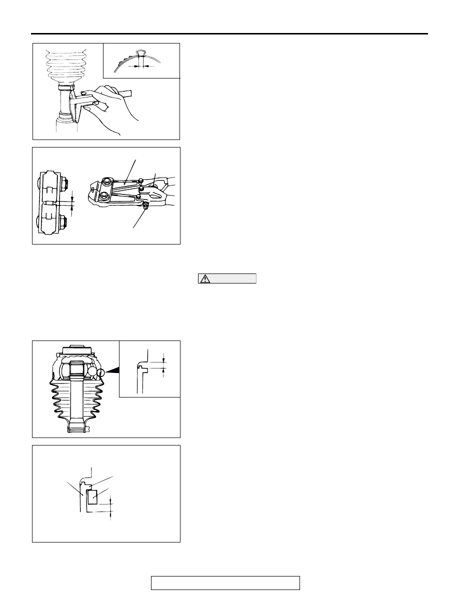
6. Check that crimping amount (B) of the BJ boot band is at the 

standard value.

Standard value (B): 2.4 

 2.8 mm (0.09  0.11 inch)

<If the crimping amount is larger than 2.8 mm (0.11 

inch)>
Readjust the value of (W) in step 3 according to the 
following formula, and then repeat the operation in 
step 5.
W = 5.5 mm (0.22 inch) 

 B 

Example: If B = 2.9 mm (0.11 inch), then W = 2.6 mm 
(0.10 inch).

<If the crimping amount is smaller than 2.4 mm (0.09 

inch)>
Remove the BJ boot band, readjust the value of 
(W) in step 3 according to the following formula, 
and then repeat the operations in steps 4 and 5 
using a new BJ boot band.
W = 5.5 mm (0.22 inch) 

 B

Example: If B = 2.3 mm (0.09 inch) then W = 3.2 mm 
(0.13 inch).

7. Check that the BJ boot band is not protruding past the place 

where it has been installed. If so, remove it and then repeat 
the operations in steps 4 to 6 using a new BJ boot band.

CAUTION

The driveshaft joint uses special grease. Do not mix old 
and new grease or different types of grease.
8. Fill the inside of the BJ boot with the specified amount of the 

specified grease.

Specified grease: Repair kit grease 120 g (4.2 oz)

9. Install the BJ boot band (large) so that there is the clearance 

(C) between it and the BJ housing is at the standard value.

Standard value (C): 0.1 

 1.55 mm (0.004  0.061 inch)

10.Follow the same procedure as in step 3 to adjust the size of 

the opening (W) shown on special tool MB991561 so that it 
is at the standard value.

Standard value (W): 3.2 mm (0.13 inch)

11.Place the BJ boot band (large) against the projection at the 

edge of the boot, and then secure it so that there is a 
clearance left as shown by (D) in the illustration.

12.Use special tool MB991561 to crimp the BJ boot band 

(large) in the same way as in step 5.

ACX00996AC

B

ACX00993AB

STOPPER

ADJUSTING BOLT

(W)

MB991561

AC001176

C

AB

AC001177

D

PROJECTION

BJ BOOT BAND

BJ BOOT

AB

DRIVE SHAFT ASSEMBLY

TSB Revision

FRONT AXLE

26-34

13.Check that the crimping amount (E) of the BJ boot band is at 

the standard value.

Standard value (E): 2.4 

 2.8 mm (0.09  0.11 inch)

<If the crimping amount is larger than 2.8 mm (0.11 

inch)>
Readjust the value of (W) in step 10 according to 
the following formula, and then repeat the opera-
tion in step 12.
W = 5.8 (0.23 inch) mm 

 E

Example: If E = 2.9 mm (0.11 inch), then W = 2.9 mm 
(0.11 inch).

 <If the crimping amount is smaller than 2.4 mm (0.09 

inch)>
Remove the BJ boot band, readjust the value of 
(W) in step 10 according to the following formula, 
and then repeat the operating in steps 11 and 12 
using a new BJ boot band.
W = 5.8 (0.23 inch) mm 

 E

Example: If E = 2.3 mm (0.09 inch), then W = 3.5mm 
(0.14 inch).

14.Check that the BJ boot band is not protruding past the place 

where it has been installed. If so, remove it and repeat the 
operations in steps 11 to 13 using a new BJ boot band.

AC004720

E

AB

ACX00993AB

STOPPER

ADJUSTING BOLT

(W)

MB991561

INNER SHAFT ASSEMBLY

TSB Revision

FRONT AXLE

26-35

INNER SHAFT ASSEMBLY

REMOVAL AND INSTALLATION

M1261004000085

Required Special Tools:

• MB990211: Sliding Hammer

• MB990906: Driveshaft Attachment

REMOVAL SERVICE POINTS

.

<<A>> CALIPER ASSEMBLY REMOVAL
Secure the removed caliper assembly with wire to prevent it 
from falling.

.

Pre-removal and Post-installation Operation
• Under Cover Removal and Installation (Refer to GROUP 

42, Under Cove

P.42-207

.)

• Gear Oil Draining and Supplying (Refer to 

P.26-14

.)

AC103693 AB

1

2

3

4

5

N

6

7

8

9

N

10

11

12

13

88 N·m
65 ft-lb

12 N·m
106 in-lb

88 N·m
65 ft-lb

12 N·m
106 in-lb

93 N·m
69 ft-lb

49 - 59 N·m
36 - 43 ft-lb

REMOVAL STEPS

 <<A>>

1.

CALIPER ASSEMBLY

2.

KNUCKLE AND HUB ASSEMBLY 
(REFER TO 

P.26-25

.)

3.

DRIVESHAFT <RH> (REFER TO 

P.26-25

.)

 <<B>> >>A<<

4. INNER 

SHAFT


5. CIRCLIP
6. PIN

7.

SPACER

8.

DIFFERENTIAL MOUNTING 
CUSHION

9.

DIFFERENTIAL MOUNTING 
BRACKET <RH>

10. BREATHER HOSE
11. BREATHER PIPE
12. HEAT PROTECTOR


13. HOUSING TUBE ASSEMBLY

REMOVAL STEPS (Continued)

INNER SHAFT ASSEMBLY

TSB Revision

FRONT AXLE

26-36

<<B>> INNER SHAFT REMOVAL

CAUTION

When pulling the inner shaft out from the front differential 
carrier, be careful that the spline part of the inner shaft 
does not damage the oil seal.
Pull the inner shaft from the differential carrier by using special 
tools MB990906 and MB990211.

INSTALLATION SERVICE POINT

.

>>A<< INNER SHAFT INSTALLATION

CAUTION

Be careful not to damage the lip of the dust seal and oil 
seal.
Drive the inner shaft into the front differential carrier by using 
special tools MB990906 and MB990211.

AC004724 AB

MB990211

MB990906

AC004724 AB

MB990211

MB990906


Content   ..  411  412  413  414   ..