Mitsubishi Montero Sport (2004+). Manual - part 224


  Index      Mitsubishi     Mitsubishi Montero Sport - service repair manual 2004 year


Search            


Content   ..  222  223  224  225   ..


Mitsubishi Montero Sport (2004+). Manual - part 224


MULTIPORT FUEL INJECTION (MFI) DIAGNOSIS

TSB Revision

MULTIPORT FUEL INJECTION (MFI)

13A-309

STEP 2. Check for exhaust leaks.
Q: Are there any abnormalities?

YES : Repair it. Then go to Step 14.
NO :  Go to Step 3.

STEP 3. Check for intake system vacuum leaks.
Q: Are there any abnormalities?

YES : Go to Step 4.
NO :  Repair it. Then go to Step 14.

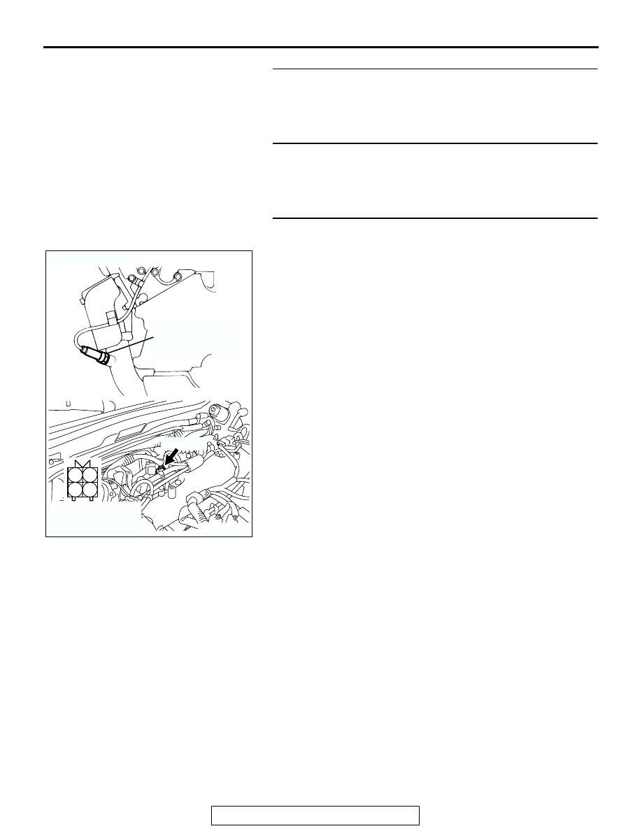
STEP 4. Check connector A-09 at the left bank heated 
oxygen sensor (front) for damage.
Q: Is the connector in good condition?

YES : Go to Step 5.
NO :  Repair or replace it. Refer to GROUP 00E, Harness 

Connector Inspection 

P.00E-2

. Then go to Step 14.

AK200496

1

2

3

4

A-09(GR)

AB

CONNECTOR: A-09

HARNESS 
CONNECTOR: 
COMPONENT SIDE

LEFT BANK
HEATED OXYGEN
SENSOR (FRONT)

MULTIPORT FUEL INJECTION (MFI) DIAGNOSIS

TSB Revision

MULTIPORT FUEL INJECTION (MFI)

13A-310

STEP 5. Check the left bank heated oxygen sensor (front).
(1) Disconnect the left bank heated oxygen sensor (front) 

connector A-09 and connect test harness special tool, 
MB991316 to the connector on the left bank heated oxygen 
sensor (front) side.

(2) Warm up the engine until engine coolant 80

°C (176°F) or 

higher.

(3) Perform a tracing for 5 minutes or more with the engine 

speed of 4,500 r/min.

(4) Connect a digital volt meter between terminal No. 2 (black 

clip) and terminal No. 4 (white clip).

(5) While repeatedly revving the engine, measure the left bank 

heated oxygen sensor (front) output voltage.

Standard value: 0.6 

 1.0 volt

CAUTION

• Be very careful when connecting the jumper wire; 

incorrect connection can damage the oxygen sensor.

• Be careful the heater is broken when voltage of beyond 

8 volts is applied to the oxygen sensor heater.
NOTE: If the sufficiently high temperature (of approximate 
400

°

C or more) is not reached although the oxygen sensor 

is normal, the output voltage would be possibly low 
although the rich air-fuel ratio. Therefore, if the output volt-
age is low, use a jumper wire to connect the terminal No.1 
(red clip of special tool) and the terminal No. 3 (blue clip of 
special tool) of the oxygen sensor with a (+) terminal and (-) 
terminal of 8 volts power supply respectively, then check 
again.

Q: Is the voltage between 0.6 and 1.0 volt?

YES : Go to Step 6.
NO :  Replace the left bank heated oxygen sensor (front). 

Then go to Step 14.

AK200496

1

2

3

4

A-09(GR)

AB

CONNECTOR: A-09

HARNESS 
CONNECTOR: 
COMPONENT SIDE

LEFT BANK
HEATED OXYGEN
SENSOR (FRONT)

AKX01624

HEATED
OXYGEN
SENSOR
COMPONENT
SIDE
CONNECTOR

MB991316

WHITE

BLACK

AN

MULTIPORT FUEL INJECTION (MFI) DIAGNOSIS

TSB Revision

MULTIPORT FUEL INJECTION (MFI)

13A-311

STEP 6. Check connector A-04 at injector intermediate 
connector for damage.
Q: Is the connector in good condition?

YES : Go to Step 7.
NO :  Repair or replace it. Refer to GROUP 00E, Harness 

Connector Inspection 

P.00E-2

. Then go to Step 14.

STEP 7. Check the left bank injector resistance at 
intermediate connector A-04.
(1) Disconnect the injector intermediate connector A-04.

(2) Measure the resistance between each injector side 

connector terminal.

a. Measure the resistance between terminal No. 2 and No. 

8 when measuring No. 2 cylinder.

b. Measure the resistance between terminal No. 7 and No. 

8 when measuring No. 4 cylinder.

c. Measure the resistance between terminal No. 5 and No. 

8 when measuring No. 6 cylinder.

• Resistance should be between 13 and 16 ohms [at 20°C 

(68

°F)].

Q: Is the measured resistance between 13 and 16 ohms [at 

20

°C (68°F)]?

YES : Go to Step 10.
NO :  Go to Step 8.

AK200014

7

2 1
6 5

4 3
8

CONNECTOR: A-04

AB

FEMALE SIDE 
CONNECTOR

A-04(B)

AK200014

7

2 1
6 5

4 3
8

CONNECTOR: A-04

AB

FEMALE SIDE 
CONNECTOR

A-04(B)

AK000533

6

3 4
7 8

1 2
5

AK000533

6

3 4
7 8

1 2
5

INJECTOR
INTERMEDIATE
CONNECTOR

AB

MULTIPORT FUEL INJECTION (MFI) DIAGNOSIS

TSB Revision

MULTIPORT FUEL INJECTION (MFI)

13A-312

STEP 8. Check connector A-70, A-71, A-72 at left bank 
injector for damage.
(1) Remove the intake manifold.
(2) Check the left bank injector connector, which deviates from 

the standard value at Step 7.

Q: Is the connector in good condition?

YES : Go to Step 9.
NO :  Repair or replace it. Refer to GROUP 00E, Harness 

Connector Inspection 

P.00E-2

. Then go to Step 14.

STEP 9. Check the left bank injector.
(1) Check the left bank injector connector, which deviates from 

the standard value at Step 7.

(2) Measure the resistance between injector side connector 

terminal No. 1 and No. 2.

Standard value: 13 

 16 ohms [at 20°C (68°F)]

Q: Is the resistance between 13 and 16 ohms [at 20

°

(68

°F)]?

YES : Repair harness wire between injector intermediate 

connector and left bank injector connector because of 
harness damage. Then go to Step 14.

NO :  Replace the injector. Then go to Step 14.

AK200016

1

2

AB

CONNECTORS: A-70, A-71, A-72

A-70(GR)

A-71(GR)

A-72(GR)

HARNESS CONNECTOR: 
COMPONENT SIDE

AK200016

1

2

AB

CONNECTORS: A-70, A-71, A-72

A-70(GR)

A-71(GR)

A-72(GR)

HARNESS CONNECTOR: 
COMPONENT SIDE

AK000456

1 2

INJECTOR SIDE
CONNECTOR

AB


Content   ..  222  223  224  225   ..