Mitsubishi Montero Sport (2004+). Manual - part 223


  Index      Mitsubishi     Mitsubishi Montero Sport - service repair manual 2004 year


Search            


Content   ..  221  222  223  224   ..


Mitsubishi Montero Sport (2004+). Manual - part 223


MULTIPORT FUEL INJECTION (MFI) DIAGNOSIS

TSB Revision

MULTIPORT FUEL INJECTION (MFI)

13A-305

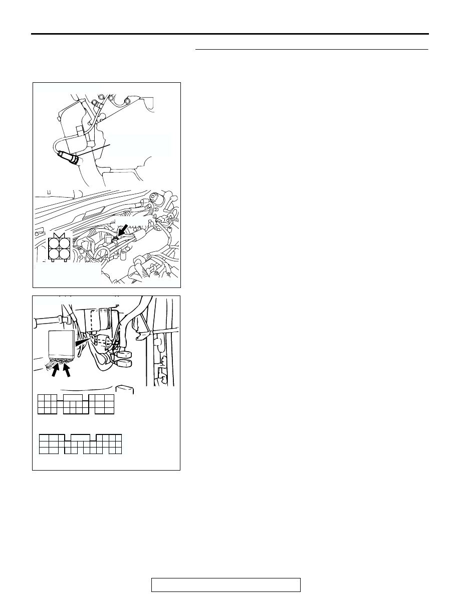
STEP 3. Check harness connector A-09 at left bank heated 
oxygen sensor (front) and harness connector C-90, C-91 at 
PCM for damage.
Q: Is the harness connector in good condition?

YES : Replace the PCM. Then go to Step 4.
NO :  Repair or replace it. Refer to GROUP 00E, Harness 

Connector Inspection 

P.00E-2

. Then go to Step 4.

AK200496

1

2

3

4

A-09(GR)

AB

CONNECTOR: A-09

HARNESS 
CONNECTOR: 
COMPONENT SIDE

LEFT BANK
HEATED OXYGEN
SENSOR (FRONT)

AK104029

42

43

48

49

50

51

52

53

54

55

56

57

46 45 44

58

59

60

61

62

63

64

65

66

47

41

98

78

71

88

89

76

77

72
79
91

73
80

74

75

81
92

82

83

93

84

85

94

86

87

95

96

90

97

AB

CONNECTORS: C-90, C-91

C-90(GR) C-91(GR)

C-90 HARNESS CONNECTOR:
COMPONENT SIDE

C-91 HARNESS CONNECTOR:
COMPONENT SIDE

MULTIPORT FUEL INJECTION (MFI) DIAGNOSIS

TSB Revision

MULTIPORT FUEL INJECTION (MFI)

13A-306

STEP 4. Test the OBD-II drive cycle.
(1) Carry out a test drive with the drive cycle pattern. Refer to 

Diagnostic Function 

− OBD-II Drive Cycle − Procedure 4 − 

Heated Oxygen Sensor Monitor 

P.13A-4

.

(2) Check the diagnostic trouble code (DTC).
Q: Is DTC P0153 set?

YES : Retry the troubleshooting.
NO :  The inspection is complete.

DTC P0154: Heated Oxygen Sensor Circuit No Activity Detected (bank 2, sensor 1)

.

Heated Oxygen Sensor Circuit No Activity 
Detected (bank 2, sensor 1) Circuit

• Refer to, DTC P0150 − Heated Oxygen Sensor 

Circuit (bank 2, sensor 1) 

P.13A-295

.

• Refer to, DTC P0201, P0202, P0203, P0204, 

P0205, P0206 

− Injector Circuit 

P.13A-428

.

.

CIRCUIT OPERATION

• Refer to, DTC P0150 − Heated Oxygen Sensor 

Circuit (bank 2, sensor 1) 

P.13A-295

.

• Refer to, DTC P0201, P0202, P0203, P0204, 

P0205, P0206 

− Injector Circuit 

P.13A-428

.

.

TECHNICAL DESCRIPTION

• The PCM effects air/fuel ratio feedback control in 

accordance with the signals from the left bank 
heater oxygen sensor (front).

• If the left bank heated oxygen sensor (front) has 

deteriorated, corrections will be made by the 
heated oxygen sensor (rear).

• DTC P0154 is stored when abnormality of the 

air/fuel ratio feedback control is detected.

.

DESCRIPTIONS OF MONITOR METHODS
Left bank heated oxygen sensor (front) output volt-

age does not cross 0.5 volt within specified 
period.

.

MONITOR EXECUTION
Continuous

.

MONITOR EXECUTION CONDITIONS (Other 
monitor and Sensor)

Other Monitor (There is no temporary DTC stored 

in memory for the item monitored below)

• Misfire monitor

Sensor (The sensor below is determined to be 

normal)

• Volume airflow sensor

• Engine coolant temperature sensor

• Intake air temperature sensor

• Barometric pressure sensor

• Throttle position sensor

.

MULTIPORT FUEL INJECTION (MFI) DIAGNOSIS

TSB Revision

MULTIPORT FUEL INJECTION (MFI)

13A-307

DTC SET CONDITIONS

Logic Flow Chart

.

Check Conditions

• 20 seconds or more have passed since the start-

ing sequence was completed.

• Engine coolant temperature is higher than 76°C 

(169

° F).

• Engine speed is higher than 1,200 r/min.

• Volumetric efficiency is higher than 30 percent 

and lower than 95 percent.

• Throttle position sensor output voltage is lower 

than 4 volts.

• Except while fuel is being shut off.

• Monitoring time: 30 seconds.

Judgment Criteria

• Left bank heated oxygen sensor (front) output 

voltage does not get across 0.5 volt within about 
30 seconds.

.

OBD-II DRIVE CYCLE PATTERN
Refer to Diagnostic Function 

− OBD-II Drive Cycle − 

Procedure 6 

− Other Monitor 

P.13A-4

.

.

HEATED OXYGEN SENSOR (FRONT) 

OUTPUT VOLTAGE CROSSES 0.5V?

START

END

NO

NO

NO

YES

Yes

YES

MALFUNCTION

GOOD

30secs HAVE PASSED?

MONITORING

CONDITIONS

AK203999

MULTIPORT FUEL INJECTION (MFI) DIAGNOSIS

TSB Revision

MULTIPORT FUEL INJECTION (MFI)

13A-308

TROUBLESHOOTING HINTS (The most likely 
causes for this code to be set are:)

• Left bank heated oxygen sensor (front) deterio-

rated.

• Open circuit in left bank heated oxygen sensor 

(front) output line.

• Open circuit in left black heated oxygen sensor 

(front) ground line.

• Left bank heated oxygen sensor (rear) deterio-

rated.
NOTE: When the left bank heated oxygen sensor 
(front) begins to deteriorate, the heated oxygen 
sensor output voltage will deviate from the volt-
age when the sensor was new (normally 0.5 volt 
at stoichiometric ratio). This deviation will be cor-
rected by the left bank heated oxygen sensor 
(rear).

If the left bank heated oxygen sensor (rear) 
responds poorly because it has deteriorated, it 
will improperly correct the left bank heated oxy-
gen sensor (front). Thus, even when closed loop 
control is being effected, the fluctuation of the left 
bank heated oxygen sensor (front) output voltage 
decreases, without intersecting with 0.5 volt. As a 
result, there is a possibility of DTC P0154 becom-
ing registered.

• Connector damage.

• Harness damage in injector circuit.

• Injector failed.

• PCM failed.

• Exhaust leaks.

• Incurrect fuel pressure.

• Intake system vacuum leak.

DIAGNOSIS

Required Special Tools:

• MB991958: Scan Tool (MUT-III Sub Assembly)

• MB991824: V.C.I

• MB991827: USB Cable

• MB991911: Main Harness B

• MB991316: Test Harness

STEP 1. Using scan tool MB991958, check data list item 59: 
Heated Oxygen Sensor Bank 2, Sensor 2 (left rear).

CAUTION

To prevent damage to scan tool MB991958, always turn the 
ignition switch to the "LOCK" (OFF) position before con-
necting or disconnecting scan tool MB991958.
(1) Connect scan tool MB991958 to the data link connector.
(2) Start the engine and run at idle.
(3) Set scan tool MB991958 to the data reading mode for item 

59, Heated Oxygen Sensor Bank 2, Sensor 2 (left rear).

• Warm up the engine. When the engine is revved, the 

output voltage should repeat 0 volt and 0.6 to 1.0 volt 
alternately.

(4) Turn the ignition switch to the "LOCK" (OFF) position.
Q: Is the sensor operating properly?

YES : Go to Step 2.
NO :  Refer to DTC P0156 

− Heated Oxygen Sensor Circuit 

(bank 2, sensor 2) 

P.13A-327

, DTC P0157 

− Heated 

Oxygen Sensor Circuit Low Voltage (bank 2, sensor 
2) 

P.13A-340

, DTC P0158-Heated Oxygen Sensor 

Circuit High Voltage (bank 2, sensor 2) 

P.13A-349

DTC P0159 

− Heated Oxygen Sensor Circuit Slow 

Response (bank 2, sensor 2) 

P.13A-355

AK303629AB

MB991911

MB991827

MB991824 

16-PIN


Content   ..  221  222  223  224   ..