Mitsubishi Galant. Manual - part 204
MULTIPORT FUEL INJECTION(MFI) DIAGNOSIS
TSB Revision
MULTIPORT FUEL INJECTION (MFI) <3.0L>
13B-41
TECHNICAL DESCRIPTION
•
The barometric pressure sensor outputs a
voltage which corresponds to the barometric
pressure.
•
The PCM checks whether this voltage is within a
specified range.
DTC SET CONDITIONS
Check Conditions
•
Two seconds or more have passed since the
starting sequence was completed.
•
Battery positive voltage is higher than 8 volts.
Judgement Criteria
•
Barometric pressure sensor output voltage has
continued to be 1.95 volts or lower
[corresponding to a barometric pressure of 50
kPa (7.3 psi) or lower] approximately 15,000 ft
above sea level for 10 seconds.
TROUBLESHOOTING HINTS (The most likely
causes for this code to be set are:)
•
Barometric pressure sensor failed.
•
Open or shorted barometric pressure sensor
circuit, or loose connector.
•
PCM failed.
DIAGNOSIS
Required Special Tools
MB991502: Scan Tool (MUT-II)
STEP 1. Using scan tool MB991502, check data list item 25:
Barometric Pressure Sensor.
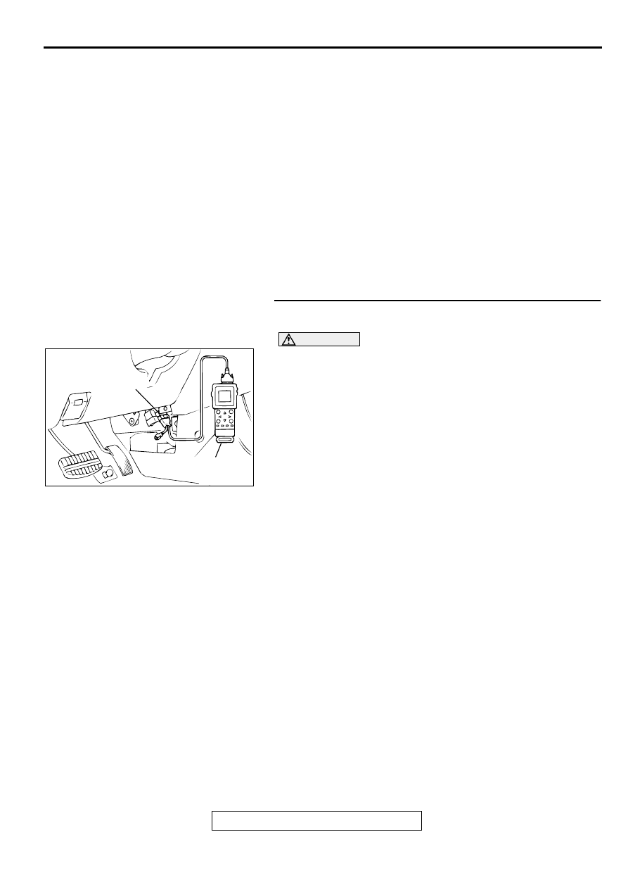
CAUTION
To prevent damage to scan tool MB991502, always turn the
ignition switch to the "LOCK"(OFF) position before
connecting or disconnecting scan tool MB991502.
(1) Connect scan tool MB991502 to the data link connector.
(2) Turn the ignition switch to the "ON" position.
(3) Set scan tool MB991502 to the data reading mode for item
25, Barometric Pressure Sensor.
•
When altitude is 0 m(0 foot), 101 kPa.
•
When altitude is 600 m(1,969 feet), 95 kPa.
•
When altitude is 1,200 m(3,937 feet), 88 kPa.
•
When altitude is 1,800 m(5,906 feet), 81 kPa.
(4) Turn the ignition switch to the "LOCK"(OFF) position.
Q: Is the sensor operating properly?
YES : It can be assumed that this malfunction is intermittent.
Refer to GROUP 00, How to Use Troubleshooting/
Inspection Service Points(
).
NO : NO: Go to Step 2.
AC003081 AB
16 PIN
MB991502