Mitsubishi Galant. Manual - part 76


  Index      Mitsubishi     Mitsubishi Galant - service repair manual 2001 year


Search            


Content   ..  74  75  76  77   ..


Mitsubishi Galant. Manual - part 76


CRANKSHAFT AND CYLINDER BLOCK

TSB Revision

ENGINE OVERHAUL <3.0L>

11D-53

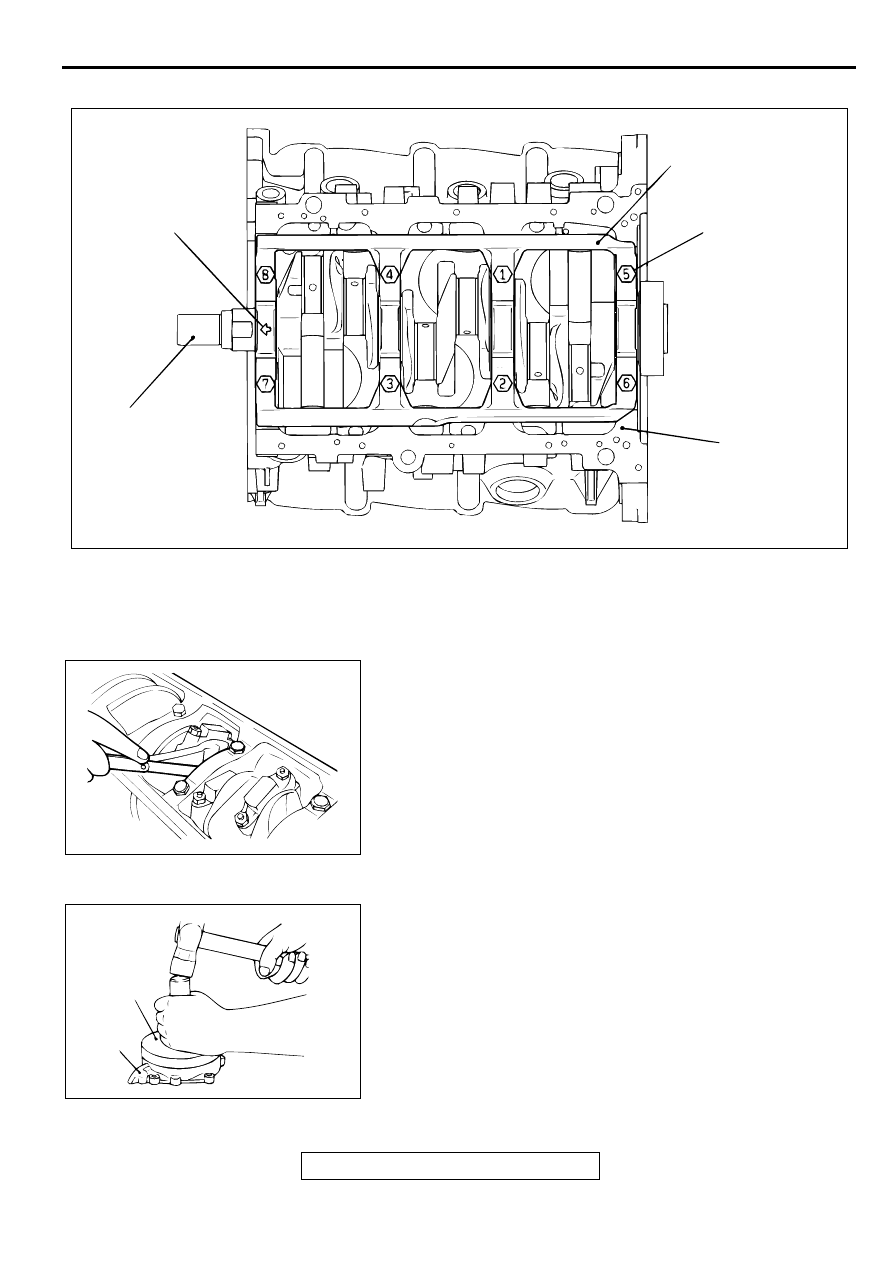
>>D<<BEARING CAP/BEARING CAP BOLT INSTALLATION

1. Install the bearing cap on the cylinder block, so that the 

arrow points to the timing belt side.

2. Tighten the bearing cap bolts to 93 N

m (69 ft-lb) in the 

specified tightening sequence.

3. Check that the crankshaft rotates smoothly.
4. Check the end play. If it exceeds the limit value, replace the 

thrust bearing.

Standard value : 0.05 

−−−−

 0.25 mm (0.002 

−−−−

 0.009 inch)

Limit: 0.3 mm (0.01 inch)

>>E<< CRANKSHAFT REAR OIL SEAL INSTALLATION
Using special tool MD998718, press-fit a new crankshaft rear 
oil seal into the oil seal case.

AKX00636

BEARING CAP

ARROW

BEARING CAP BOLT NO.
TIGHTENING SEQUENCE

CRANKSHAFT

CYLINDER BLOCK

AB

AKX00722

AKX00693

MD998718

OIL SEAL 
CASE

AB

CRANKSHAFT AND CYLINDER BLOCK

TSB Revision

ENGINE OVERHAUL <3.0L>

11D-54

>>F<< OIL SEAL CASE ASSEMBLY INSTALLATION
1. Apply sealant Mitsubishi Genuine Part number MD970389 

or equivalent to the gasket surface of oil seal case.

NOTE: Be sure to install the case quickly while the sealant is 
wet (within 15 minutes).

2. Apply engine oil to the lip of the oil seal, and then install the 

oil seal case onto the cylinder block.

NOTE: After installation, keep the sealed area away from 
the oil for approximately one hour.

INSPECTION

M1113008800043

CRANKSHAFT JOURNAL OIL CLEARANCE (PLASTIC 
GAUGING MATERIAL METHOD)
1. Remove oil from the crankshaft journal and crankshaft 

bearing.

2. Install the crankshaft.

3. Cut plastic gauging material to the same length as the width 

of the bearing and place it on the journal in parallel with its 
axis.

4. Install the crankshaft bearing cap carefully and tighten the 

bolts to the specified torque.

5. Carefully remove the crankshaft bearing cap.

6. Measure the width of the plastic gauging material at its 

widest part by using a scale printed on the plastic gauging 
material package.

Standard value: 0.02 

−−−−

 0.04 mm (0.0008 

−−−−

 0.0015 inch)

Limit: 0.1 mm (0.003 inch)

CYLINDER BLOCK 
1. Visually check for scratches, rust, and corrosion. Use also a 

flaw detecting agent for the check. If defects are evident, 
correct, or replace.

2. Using a straightedge and feeler gauge, check the block top 

surface for warpage. Make sure that the surface is free from 
gasket chips and other foreign matter.

Standard value: 0.05 mm (0.002 inch)
Limit: 0.1 mm (0.003 inch)

3. If the distortion is excessive, correct within the allowable 

limit or replace.

Grinding limit: 0.2 mm (0.008 inch) 

*Includes/combined with cylinder head grinding.

AKX00741

AKX00737AB

PLASTIC GAUGING
MATERIAL

AKX00724

AKX00738

CRANKSHAFT AND CYLINDER BLOCK

TSB Revision

ENGINE OVERHAUL <3.0L>

11D-55

Cylinder block height (when new): 

210.5 mm (8.29 inches)

4. Check the cylinder walls for scratches and seizure. If defects 

are evident, replace or bore to oversize and replace pistons 
and piston rings.

5. Using a cylinder gauge, measure the cylinder bore and 

cylindricity. If worn badly, correct by boring the cylinders to 
an oversize and replace pistons and piston rings. Measure 
at the points shown in the illustration.

Standard value: 

Cylinder Inside Diameter: 91.1 mm (3.59 inches)
Cylindricity: 0.01 mm (0.0003 inch)

BORING CYLINDER
1. Oversize pistons to be used should be determined on the 

basis of the largest bore cylinder.
Piston size identification

NOTE: Size mark is stamped on the piston top.

2. Measure the outside diameter of the piston to be used. 

Measure it in the thrust direction as shown.

3. Based on the measured piston Outside Diameter (OD), 

calculate the boring finish dimension.

Boring finish dimension = 

Piston OD + (clearance between piston OD and 

cylinder) 

−−−−

 0.02 mm (0.0008 inch) (honing margin)

CAUTION

To prevent distortion that may result from temperature rise 
during honing, bore cylinders in the order of number 2, 
number 4, number 6, number 1, number 3 and number 5.
4. Bore all cylinders to the calculated boring finish dimension.

5. Hone to the final finish dimension (piston OD + clearance 

between piston OD and cylinder).

6. Check the clearance between the piston and cylinder.

Clearance between piston and cylinder: 

0.02 

−−−−

 0.04 mm (0.0008 -.0015 inch)

NOTE: When boring cylinders, finish all of six cylinders to 
the same oversize. Do not bore only one cylinder to an 
oversize.

AKX00739

12 mm (0.47 in)

CENTER

AB

BOTTOM

SIZE

IDENTIFICATION 
MARK

0.50 mm (0.02 in) Oversize diameter

0.50

1.00 mm (0.04 in) Oversize diameter

1.00

AKX00740

PISTON OD

THRUST 
DIRECTION

AB

SPECIFICATIONS

TSB Revision

ENGINE OVERHAUL <3.0L>

11D-56

SPECIFIC ATIO NS

FASTENER TIGHTENING SPECIFICATIONS

M1113023400105

ITEMS

SPECIFICATIONS

Generator and drive belt

Crankshaft bolt

181 N

m (134 ft-lb)

Dipstick guide bolt

48 N

m (35 ft-lb)

Drive belt tensioner pulley nut

49  N

m (36 ft-lb)

Generator bolt nut

44 N

m (33 ft-lb)

Generator bolt M8

22 N

m (16 ft-lb)

Generator bracket bolt

49 N

m (36 ft-lb)

Intake manifold plenum and throttle body

Exhaust gas recirculation pipe bolt

18 N

m (13 ft-lb)

Exhaust gas recirculation pipe flare nut

59 N

m (43 ft-lb)

Exhaust gas recirculation valve bolt

22 N

m (16 ft-lb)

Intake manifold plenum stay M8

18 N

m (13 ft-lb)

Intake manifold plenum bolt and nut

18 N

m (13 ft-lb)

Intake manifold plenum stay M10

35 N

m (26 ft-lb)

Manifold differential pressure sensor

4.9 N

m (43 in-lb)

Throttle body bolt

12 N

m (104 in-lb)

Ignition system

Distributor

13 N

m (113 in-lb)

Spark plugs

25 N

m (18 ft-lb)

Timing belt

Auto tensioner bolt

24 N

m (17 ft-lb)

Bracket

24 N

m (17 ft-lb)

Camshaft sprocket bolt

88 N

m (65 ft-lb)

Crankshaft position sensor bolt

8.8 N

m (78 in-lb)

Engine support bracket

44 N

m (33 ft-lb)

Idler pulley bolt

44 N

m (33 ft-lb)

Tensioner pulley bolt

48 N

m (35 ft-lb)

Tensioner arm bolt

44 N

m (33 ft-lb)

Timing belt cover bolt M6

11 N

m (95 in-lb)

Timing belt cover bolt M8

14 N

m (122 in-lb)

Timing belt rear cover bolt

14 N

m (122 in-lb)

Intake manifold and fuel parts

Fuel rail bolt

12 N

m (104 in-lb)

Fuel pressure regulator bolt

8.8 N

m (78 in-lb)

Intake manifold nut

22 N

m (16 ft-lb)

Water pump and water pipes

Engine coolant temperature gauge unit

11 N

m (95 in-lb)


Content   ..  74  75  76  77   ..